GE Power Management 750/760 Feeder Management Relay 13-
35
13 S6 MONITORING 13.8 EQUIPMENT
13
13.8.5 COIL MONITOR
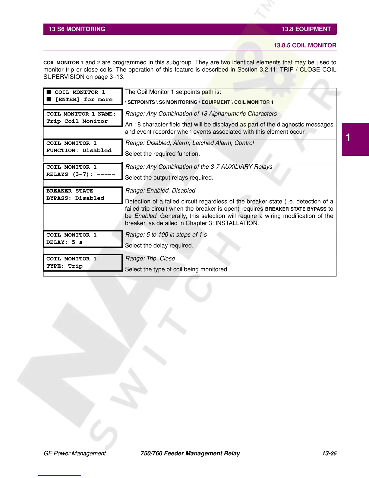
COIL MONITOR 1
and
2
are programmed in this subgroup. They are two identical elements that may be used to
monitor trip or close coils. The operation of this feature is described in Section 3.2.11: TRIP / CLOSE COIL
SUPERVISION on page 3–13.
■ COIL MONITOR 1
■ [ENTER] for more
The Coil Monitor 1 setpoints path is:
\ SETPOINTS \ S6 MONITORING \ EQUIPMENT \ COIL MONITOR 1
COIL MONITOR 1 NAME:
Trip Coil Monitor
Range: Any Combination of 18 Alphanumeric Characters
An 18 character field that will be displayed as part of the diagnostic messages
and event recorder when events associated with this element occur.
COIL MONITOR 1
FUNCTION: Disabled
Range: Disabled, Alarm, Latched Alarm, Control
Select the required function.
COIL MONITOR 1
RELAYS (3-7): -----
Range: Any Combination of the 3-7 AUXILIARY Relays
Select the output relays required.
BREAKER STATE
BYPASS: Disabled
Range: Enabled, Disabled
Detection of a failed circuit regardless of the breaker state (i.e. detection of a
failed trip circuit when the breaker is open) requires
BREAKER STATE BYPASS
to
be
Enabled
. Generally, this selection will require a wiring modification of the
breaker, as detailed in Chapter 3: INSTALLATION.
COIL MONITOR 1
DELAY: 5 s
Range: 5 to 100 in steps of 1 s
Select the delay required.
COIL MONITOR 1
TYPE: Trip
Range: Trip, Close
Select the type of coil being monitored.
 Loading...


