GE Power Management 750/760 Feeder Management Relay 12-
45
12 S5 PROTECTION 12.6 NEGATIVE SEQUENCE
12
12.6.4 NEGATIVE SEQUENCE DIRECTIONAL
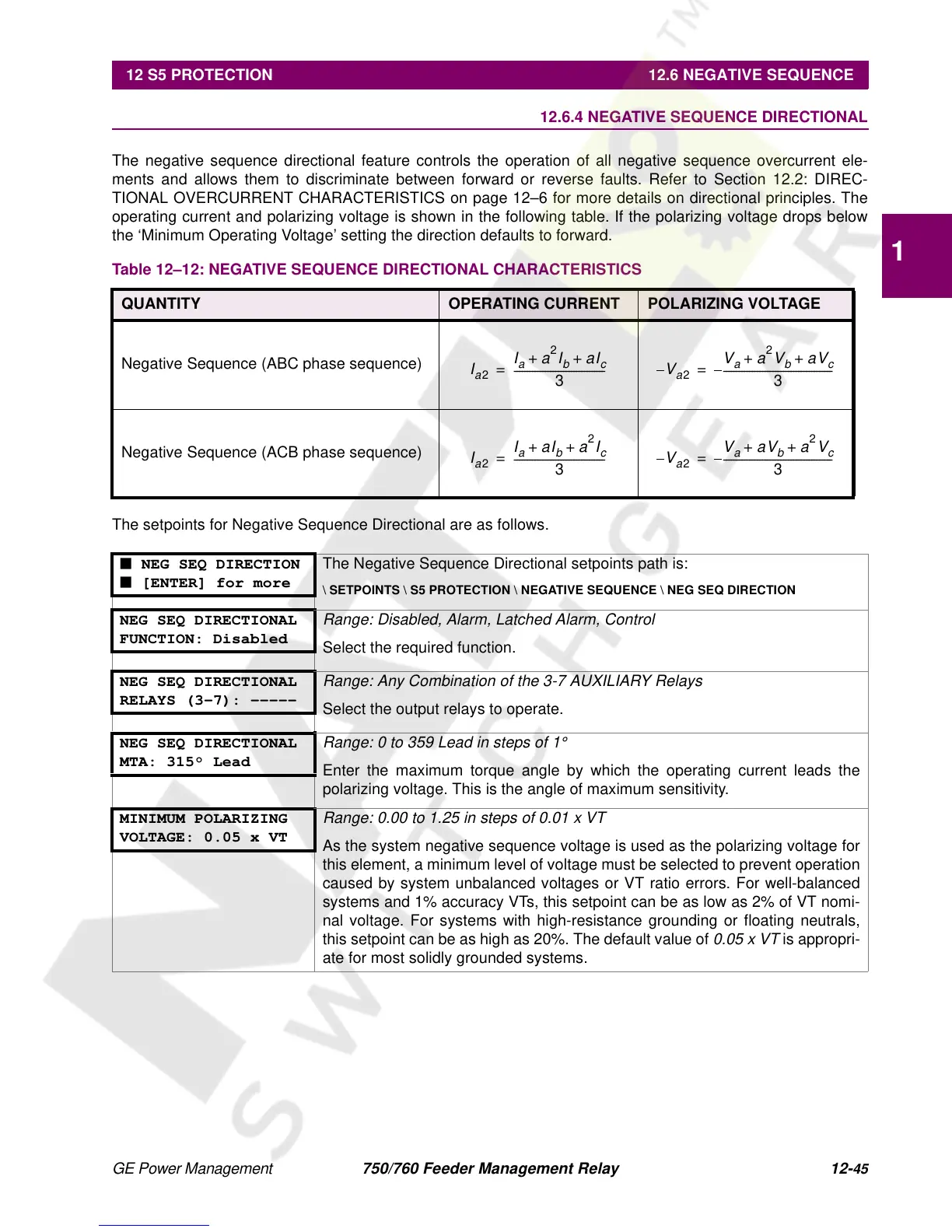
The negative sequence directional feature controls the operation of all negative sequence overcurrent ele-
ments and allows them to discriminate between forward or reverse faults. Refer to Section 12.2: DIREC-
TIONAL OVERCURRENT CHARACTERISTICS on page 12–6 for more details on directional principles. The
operating current and polarizing voltage is shown in the following table. If the polarizing voltage drops below
the ‘Minimum Operating Voltage’ setting the direction defaults to forward.
The setpoints for Negative Sequence Directional are as follows.
Table 12–12: NEGATIVE SEQUENCE DIRECTIONAL CHARACTERISTICS
QUANTITY OPERATING CURRENT POLARIZING VOLTAGE
Negative Sequence (ABC phase sequence)
Negative Sequence (ACB phase sequence)
■ NEG SEQ DIRECTION
■ [ENTER] for more
The Negative Sequence Directional setpoints path is:
\ SETPOINTS \ S5 PROTECTION \ NEGATIVE SEQUENCE \ NEG SEQ DIRECTION
NEG SEQ DIRECTIONAL
FUNCTION: Disabled
Range: Disabled, Alarm, Latched Alarm, Control
Select the required function.
NEG SEQ DIRECTIONAL
RELAYS (3-7): -----
Range: Any Combination of the 3-7 AUXILIARY Relays
Select the output relays to operate.
NEG SEQ DIRECTIONAL
MTA: 315° Lead
Range: 0 to 359 Lead in steps of 1
°
Enter the maximum torque angle by which the operating current leads the
polarizing voltage. This is the angle of maximum sensitivity.
MINIMUM POLARIZING
VOLTAGE: 0.05 x VT
Range: 0.00 to 1.25 in steps of 0.01 x VT
As the system negative sequence voltage is used as the polarizing voltage for
this element, a minimum level of voltage must be selected to prevent operation
caused by system unbalanced voltages or VT ratio errors. For well-balanced
systems and 1% accuracy VTs, this setpoint can be as low as 2% of VT nomi-
nal voltage. For systems with high-resistance grounding or floating neutrals,
this setpoint can be as high as 20%. The default value of
0.05 x VT
is appropri-
ate for most solidly grounded systems.
I
a
2
I
a
a
2
I
b
aI
c
++
3
-----------------------------------
=
a
2
V
a
a
2
V
b
3
------------------------------------------
I
a
2
I
a
aI
b
a
2
I
c
++
3
-----------------------------------
=
a
2
V
a
b
3
------------------------------------------
 Loading...


