GE Power Management 750/760 Feeder Management Relay 17-
25
17 COMMISSIONING 17.7 PROTECTION SCHEMES
17
17.7.7 PHASE DIRECTIONAL OVERCURRENT
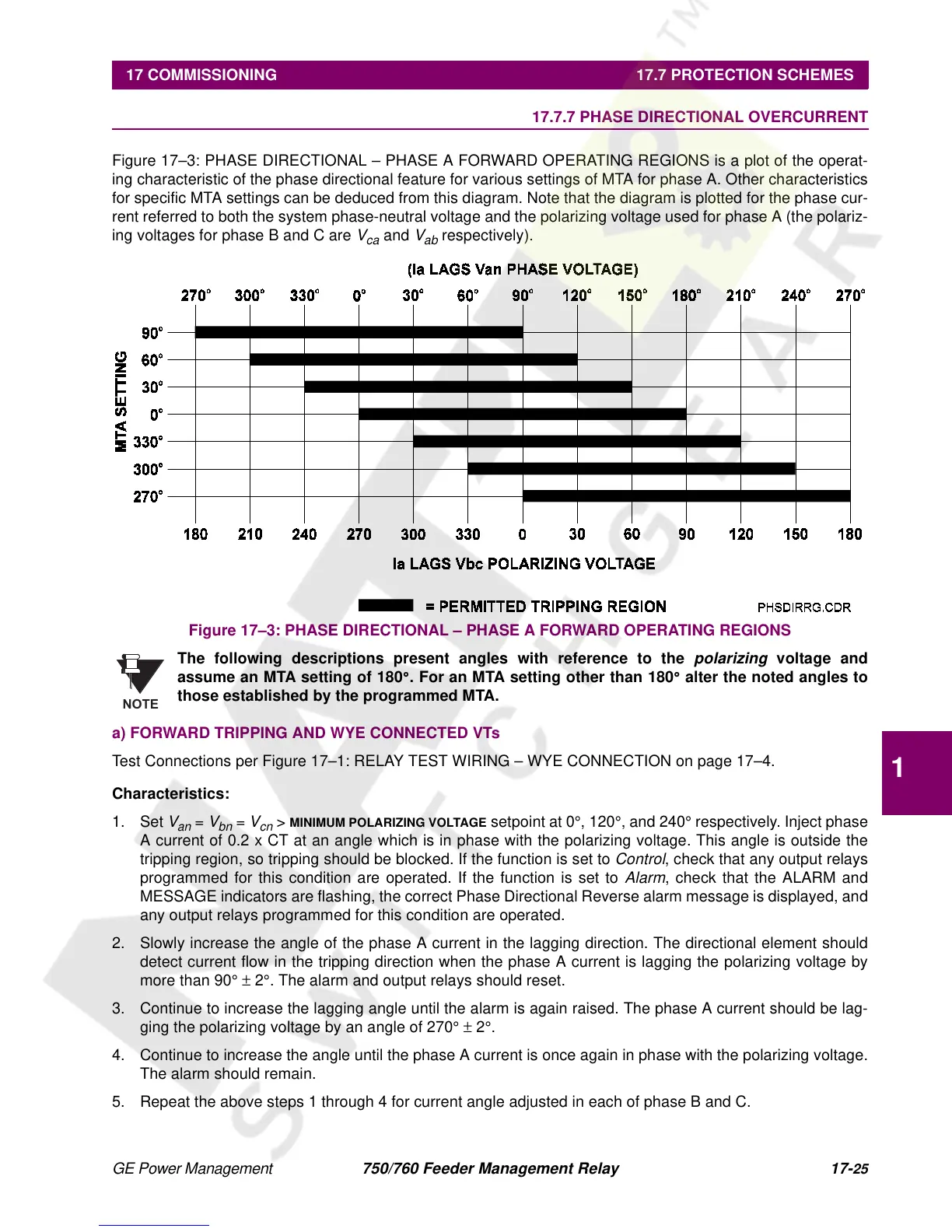
Figure 17–3: PHASE DIRECTIONAL – PHASE A FORWARD OPERATING REGIONS is a plot of the operat-
ing characteristic of the phase directional feature for various settings of MTA for phase A. Other characteristics
for specific MTA settings can be deduced from this diagram. Note that the diagram is plotted for the phase cur-
rent referred to both the system phase-neutral voltage and the polarizing voltage used for phase A (the polariz-
ing voltages for phase B and C are
V
ca
and
V
ab
respectively).
Figure 17–3: PHASE DIRECTIONAL – PHASE A FORWARD OPERATING REGIONS
The following descriptions present angles with reference to the
polarizing
voltage and
assume an MTA setting of 180
°
. For an MTA setting other than 180
°
alter the noted angles to
those established by the programmed MTA.
a) FORWARD TRIPPING AND WYE CONNECTED VTs
Test Connections per Figure 17–1: RELAY TEST WIRING – WYE CONNECTION on page 17–4.
Characteristics:
1. Set
V
an
=
V
bn
=
V
cn
>
MINIMUM POLARIZING VOLTAGE
setpoint at 0
°
, 120
°
, and 240
°
respectively. Inject phase
A current of 0.2 x CT at an angle which is in phase with the polarizing voltage. This angle is outside the
tripping region, so tripping should be blocked. If the function is set to
Control
, check that any output relays
programmed for this condition are operated. If the function is set to
Alarm
, check that the ALARM and
MESSAGE indicators are flashing, the correct Phase Directional Reverse alarm message is displayed, and
any output relays programmed for this condition are operated.
2. Slowly increase the angle of the phase A current in the lagging direction. The directional element should
detect current flow in the tripping direction when the phase A current is lagging the polarizing voltage by
more than 90
°
±
2
°
. The alarm and output relays should reset.
3. Continue to increase the lagging angle until the alarm is again raised. The phase A current should be lag-
ging the polarizing voltage by an angle of 270
°
±
2
°
.
4. Continue to increase the angle until the phase A current is once again in phase with the polarizing voltage.
The alarm should remain.
5. Repeat the above steps 1 through 4 for current angle adjusted in each of phase B and C.
NOTE
 Loading...


