6-
4
750/760 Feeder Management Relay GE Power Management
6.2 A1 STATUS 6 ACTUAL VALUES
6
6.2 A1 STATUS 6.2.1 DESCRIPTION
Some status information is displayed by the front panel indicators. More status details can be viewed from the
first page of actual values. This information includes time and date, the state of virtual and hardware logic
inputs, data captured at the time of the last trip, fault locator data, and autoreclosure scheme data for 760
users.
6.2.2 VIRTUAL INPUTS
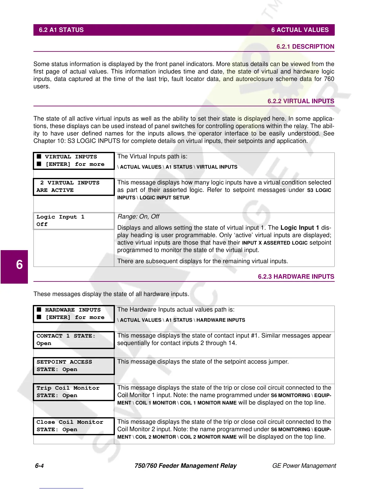
The state of all active virtual inputs as well as the ability to set their state is displayed here. In some applica-
tions, these displays can be used instead of panel switches for controlling operations within the relay. The abil-
ity to have user defined names for the inputs allows the operator interface to be easily understood. See
Chapter 10: S3 LOGIC INPUTS for complete details on virtual inputs, their setpoints and application.
6.2.3 HARDWARE INPUTS
These messages display the state of all hardware inputs.
■ VIRTUAL INPUTS
■ [ENTER] for more
The Virtual Inputs path is:
\ ACTUAL VALUES \ A1 STATUS \ VIRTUAL INPUTS
2 VIRTUAL INPUTS
ARE ACTIVE
This message displays how many logic inputs have a virtual condition selected
as part of their asserted logic. Refer to setpoint messages under
S3 LOGIC
INPUTS \ LOGIC INPUT SETUP
.
Logic Input 1
Off
Range: On, Off
Displays and allows setting the state of virtual input 1. The
Logic Input 1
dis-
play heading is user programmable. Only ‘active’ virtual inputs are displayed;
active virtual inputs are those that have their
INPUT X ASSERTED LOGIC
setpoint
programmed to monitor the state of the virtual input.
There are subsequent displays for the remaining virtual inputs.
■ HARDWARE INPUTS
■ [ENTER] for more
The Hardware Inputs actual values path is:
\ ACTUAL VALUES \ A1 STATUS \ HARDWARE INPUTS
CONTACT 1 STATE:
Open
This message displays the state of contact input #1. Similar messages appear
sequentially for contact inputs 2 through 14.
SETPOINT ACCESS
STATE: Open
This message displays the state of the setpoint access jumper.
Trip Coil Monitor
STATE: Open
This message displays the state of the trip or close coil circuit connected to the
Coil Monitor 1 input. Note: the name programmed under
S6 MONITORING \ EQUIP-
MENT \ COIL 1 MONITOR \ COIL 1 MONITOR NAME
will be displayed on the top line.
Close Coil Monitor
STATE: Open
This message displays the state of the trip or close coil circuit connected to the
Coil Monitor 2 input. Note: the name programmed under
S6 MONITORING \ EQUIP-
MENT \ COIL 2 MONITOR \ COIL 2 MONITOR NAME
will be displayed on the top line.
 Loading...


