GE Power Management 750/760 Feeder Management Relay 6
-
9
6 ACTUAL VALUES 6.3 A2 METERING
6
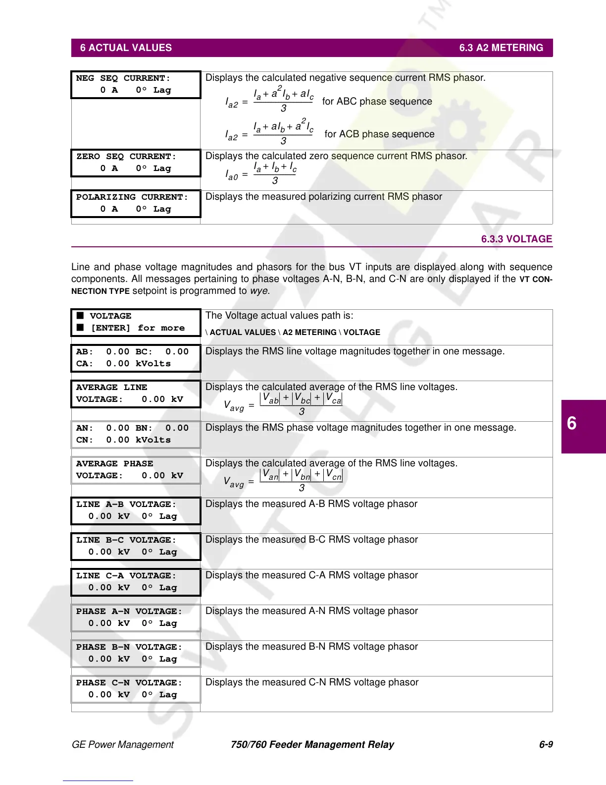
6.3.3 VOLTAGE
Line and phase voltage magnitudes and phasors for the bus VT inputs are displayed along with sequence
components. All messages pertaining to phase voltages A-N, B-N, and C-N are only displayed if the
VT CON-
NECTION TYPE
setpoint is programmed to
wye
.
NEG SEQ CURRENT:
0 A 0° Lag
Displays the calculated negative sequence current RMS phasor.
ZERO SEQ CURRENT:
0 A 0° Lag
Displays the calculated zero sequence current RMS phasor.
POLARIZING CURRENT:
0 A 0° Lag
Displays the measured polarizing current RMS phasor
■ VOLTAGE
■ [ENTER] for more
The Voltage actual values path is:
\ ACTUAL VALUES \ A2 METERING \ VOLTAGE
AB: 0.00 BC: 0.00
CA: 0.00 kVolts
Displays the RMS line voltage magnitudes together in one message.
AVERAGE LINE
VOLTAGE: 0.00 kV
Displays the calculated average of the RMS line voltages.
AN: 0.00 BN: 0.00
CN: 0.00 kVolts
Displays the RMS phase voltage magnitudes together in one message.
AVERAGE PHASE
VOLTAGE: 0.00 kV
Displays the calculated average of the RMS line voltages.
LINE A-B VOLTAGE:
0.00 kV 0° Lag
Displays the measured A-B RMS voltage phasor
LINE B-C VOLTAGE:
0.00 kV 0° Lag
Displays the measured B-C RMS voltage phasor
LINE C-A VOLTAGE:
0.00 kV 0° Lag
Displays the measured C-A RMS voltage phasor
PHASE A-N VOLTAGE:
0.00 kV 0° Lag
Displays the measured A-N RMS voltage phasor
PHASE B-N VOLTAGE:
0.00 kV 0° Lag
Displays the measured B-N RMS voltage phasor
PHASE C-N VOLTAGE:
0.00 kV 0° Lag
Displays the measured C-N RMS voltage phasor
I
a2
I
a
a
2
I
b
aI
c
++
3
------------------------------------ for ABC phase sequence =
I
a2
I
a
aI
b
a
2
I
c
++
3
------------------------------------ for ACB phase sequence=
I
a0
I
a
I
b
I
c
++
3
--------------------------=
V
avg
V
ab
V
bc
V
ca
++
3
--------------------------------------------------=
V
avg
V
an
V
bn
V
cn
++
3
---------------------------------------------------=
 Loading...


