GE Power Management 750/760 Feeder Management Relay 16-
17
16 COMMUNICATIONS 16.3 MODBUS PROTOCOL
16
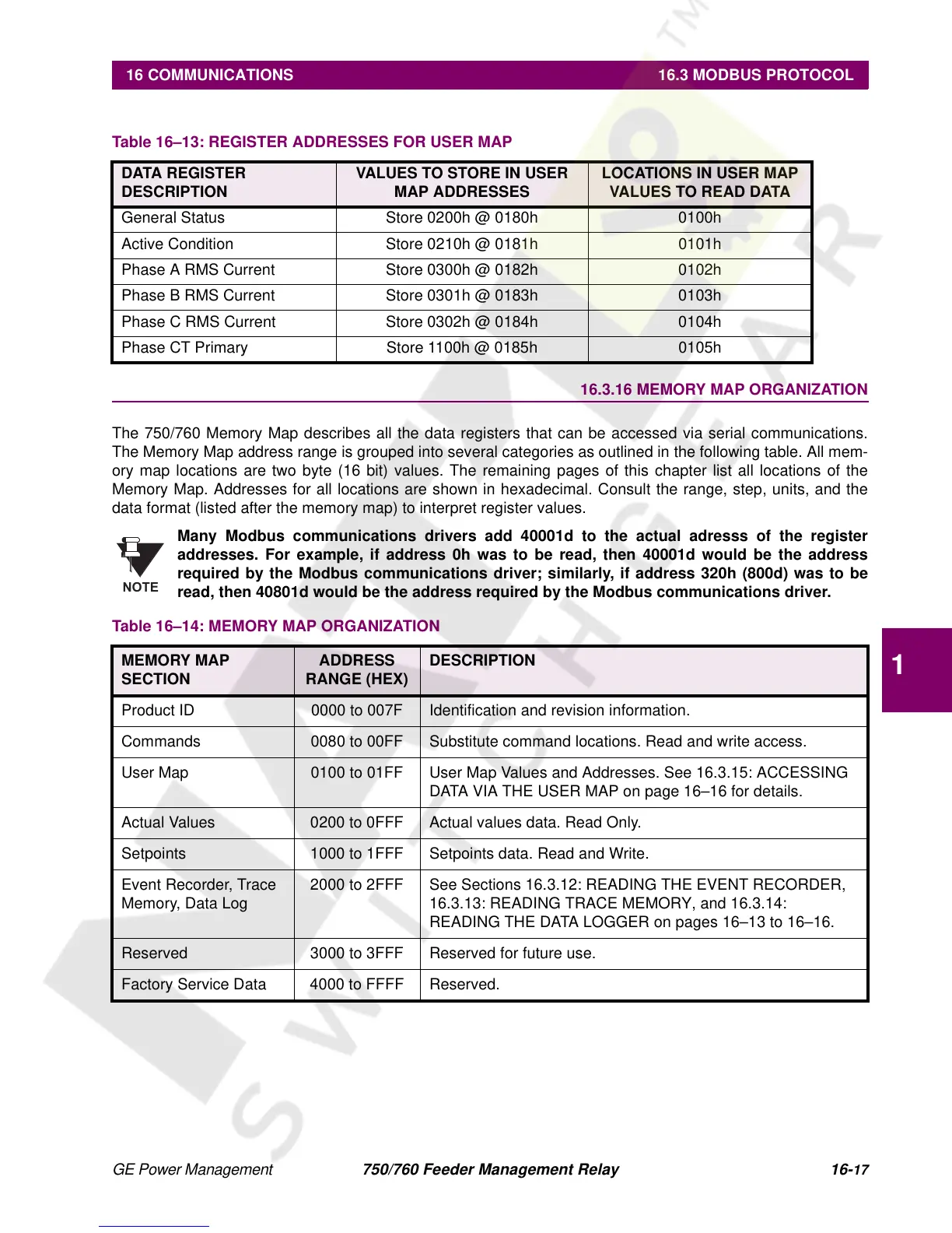
16.3.16 MEMORY MAP ORGANIZATION
The 750/760 Memory Map describes all the data registers that can be accessed via serial communications.
The Memory Map address range is grouped into several categories as outlined in the following table. All mem-
ory map locations are two byte (16 bit) values. The remaining pages of this chapter list all locations of the
Memory Map. Addresses for all locations are shown in hexadecimal. Consult the range, step, units, and the
data format (listed after the memory map) to interpret register values.
Many Modbus communications drivers add 40001d to the actual adresss of the register
addresses.
For example, if address 0h was to be read, then 40001d would be the address
required by the Modbus communications driver; similarly, if address 320h (800d) was to be
read, then 40801d would be the address required by the Modbus communications driver.
Table 16–13: REGISTER ADDRESSES FOR USER MAP
DATA REGISTER
DESCRIPTION
VALUES TO STORE IN USER
MAP ADDRESSES
LOCATIONS IN USER MAP
VALUES TO READ DATA
General Status Store 0200h @ 0180h 0100h
Active Condition Store 0210h @ 0181h 0101h
Phase A RMS Current Store 0300h @ 0182h 0102h
Phase B RMS Current Store 0301h @ 0183h 0103h
Phase C RMS Current Store 0302h @ 0184h 0104h
Phase CT Primary Store 1100h @ 0185h 0105h
Table 16–14: MEMORY MAP ORGANIZATION
MEMORY MAP
SECTION
ADDRESS
RANGE (HEX)
DESCRIPTION
Product ID 0000 to 007F Identification and revision information.
Commands 0080 to 00FF Substitute command locations. Read and write access.
User Map 0100 to 01FF User Map Values and Addresses. See 16.3.15: ACCESSING
DATA VIA THE USER MAP on page 16–16 for details.
Actual Values 0200 to 0FFF Actual values data. Read Only.
Setpoints 1000 to 1FFF Setpoints data. Read and Write.
Event Recorder, Trace
Memory, Data Log
2000 to 2FFF See Sections 16.3.12: READING THE EVENT RECORDER,
16.3.13: READING TRACE MEMORY, and 16.3.14:
READING THE DATA LOGGER on pages 16–13 to 16–16.
Reserved 3000 to 3FFF Reserved for future use.
Factory Service Data 4000 to FFFF Reserved.
NOTE
 Loading...


