12-
14
750/760 Feeder Management Relay GE Power Management
12.2 DIRECTIONAL OVERCURRENT CHARACTERISTICS 12 S5 PROTECTION
12
12.2.6 PHASE DIRECTIONAL SETPOINTS
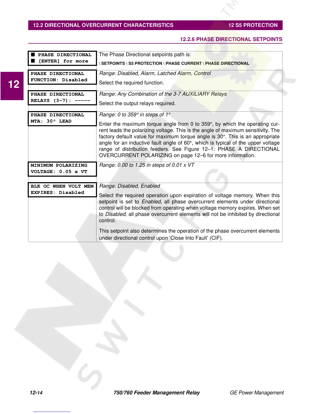
■ PHASE DIRECTIONAL
■ [ENTER] for more
The Phase Directional setpoints path is:
\ SETPOINTS \ S5 PROTECTION \ PHASE CURRENT \ PHASE DIRECTIONAL
PHASE DIRECTIONAL
FUNCTION: Disabled
Range: Disabled, Alarm, Latched Alarm, Control
Select the required function.
PHASE DIRECTIONAL
RELAYS (3-7): -----
Range: Any Combination of the 3-7 AUXILIARY Relays
Select the output relays required.
PHASE DIRECTIONAL
MTA: 30° LEAD
Range: 0 to 359° in steps of 1
°
Enter the maximum torque angle from 0 to 359°, by which the operating cur-
rent leads the polarizing voltage. This is the angle of maximum sensitivity. The
factory default value for maximum torque angle is 30°. This is an appropriate
angle for an inductive fault angle of 60°, which is typical of the upper voltage
range of distribution feeders. See Figure 12–1: PHASE A DIRECTIONAL
OVERCURRENT POLARIZING on page 12–6 for more information.
MINIMUM POLARIZING
VOLTAGE: 0.05 x VT
Range: 0.00 to 1.25 in steps of 0.01 x VT
BLK OC WHEN VOLT MEM
EXPIRES: Disabled
Range: Disabled, Enabled
Select the required operation upon expiration of voltage memory. When this
setpoint is set to
Enabled
, all phase overcurrent elements under directional
control will be blocked from operating when voltage memory expires. When set
to
Disabled
, all phase overcurrent elements will not be inhibited by directional
control.
This setpoint also determines the operation of the phase overcurrent elements
under directional control upon ‘Close Into Fault’ (CIF).
 Loading...


