GE Power Management 750/760 Feeder Management Relay 15-
9
15 S8 TESTING 15.4 SIMULATION
15
15.4.5 POSTFAULT VALUES
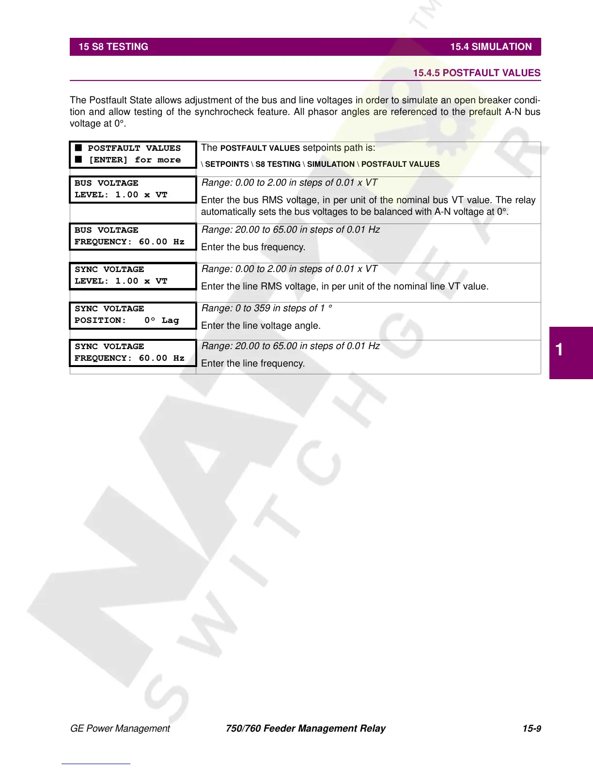
The Postfault State allows adjustment of the bus and line voltages in order to simulate an open breaker condi-
tion and allow testing of the synchrocheck feature. All phasor angles are referenced to the prefault A-N bus
voltage at 0°.
■ POSTFAULT VALUES
■ [ENTER] for more
The
POSTFAULT VALUES
setpoints path is:
\ SETPOINTS \ S8 TESTING \ SIMULATION \ POSTFAULT VALUES
BUS VOLTAGE
LEVEL: 1.00 x VT
Range: 0.00 to 2.00 in steps of 0.01 x VT
Enter the bus RMS voltage, in per unit of the nominal bus VT value. The relay
automatically sets the bus voltages to be balanced with A-N voltage at 0°.
BUS VOLTAGE
FREQUENCY: 60.00 Hz
Range: 20.00 to 65.00 in steps of 0.01 Hz
Enter the bus frequency.
SYNC VOLTAGE
LEVEL: 1.00 x VT
Range: 0.00 to 2.00 in steps of 0.01 x VT
Enter the line RMS voltage, in per unit of the nominal line VT value.
SYNC VOLTAGE
POSITION: 0° Lag
Range: 0 to 359 in steps of 1 °
Enter the line voltage angle.
SYNC VOLTAGE
FREQUENCY: 60.00 Hz
Range: 20.00 to 65.00 in steps of 0.01 Hz
Enter the line frequency.
 Loading...


