9-
2
750/760 Feeder Management Relay GE Power Management
9.2 BUS VT SENSING 9 S2 SYSTEM SETUP
9
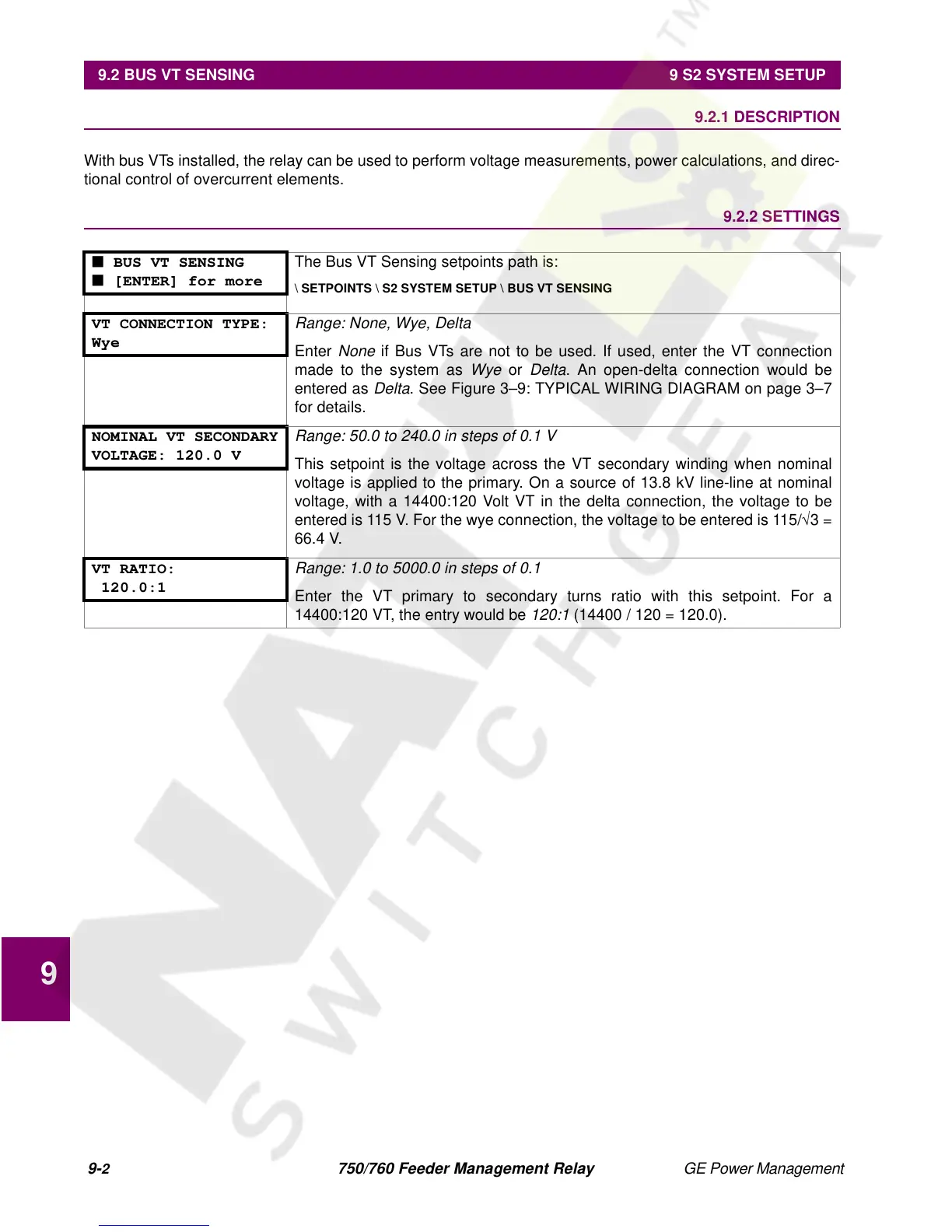
9.2 BUS VT SENSING 9.2.1 DESCRIPTION
With bus VTs installed, the relay can be used to perform voltage measurements, power calculations, and direc-
tional control of overcurrent elements.
9.2.2 SETTINGS
■ BUS VT SENSING
■ [ENTER] for more
The Bus VT Sensing setpoints path is:
\ SETPOINTS \ S2 SYSTEM SETUP \ BUS VT SENSING
VT CONNECTION TYPE:
Wye
Range: None, Wye, Delta
Enter
None
if Bus VTs are not to be used. If used, enter the VT connection
made to the system as
Wye
or
Delta
. An open-delta connection would be
entered as
Delta
. See Figure 3–9: TYPICAL WIRING DIAGRAM on page 3–7
for details.
NOMINAL VT SECONDARY
VOLTAGE: 120.0 V
Range: 50.0 to 240.0 in steps of 0.1 V
This setpoint is the voltage across the VT secondary winding when nominal
voltage is applied to the primary. On a source of 13.8 kV line-line at nominal
voltage, with a 14400:120 Volt VT in the delta connection, the voltage to be
entered is 115 V. For the wye connection, the voltage to be entered is 115/
√
3 =
66.4 V.
VT RATIO:
120.0:1
Range: 1.0 to 5000.0 in steps of 0.1
Enter the VT primary to secondary turns ratio with this setpoint. For a
14400:120 VT, the entry would be
120:1
(14400 / 120 = 120.0).
 Loading...


