GE Power Management 750/760 Feeder Management Relay 2-
5
2 GETTING STARTED 2.3 SAMPLE APPLICATION
2
2.3 SAMPLE APPLICATION 2.3.1 APPLICATION EXAMPLE
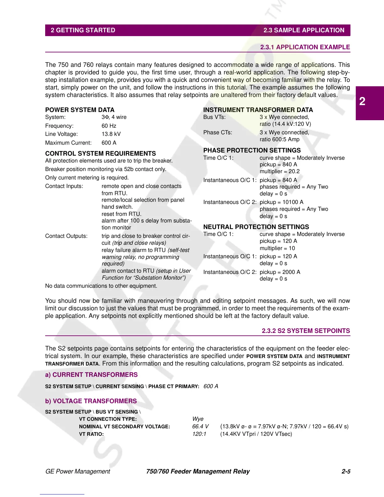
The 750 and 760 relays contain many features designed to accommodate a wide range of applications. This
chapter is provided to guide you, the first time user, through a real-world application. The following step-by-
step installation example, provides you with a quick and convenient way of becoming familiar with the relay. To
start, simply power on the unit, and follow the instructions in this tutorial. The example assumes the following
system characteristics. It also assumes that relay setpoints are unaltered from their factory default values.
POWER SYSTEM DATA
System: 3
Φ
, 4 wire
Frequency: 60 Hz
Line Voltage: 13.8 kV
Maximum Current: 600 A
CONTROL SYSTEM REQUIREMENTS
All protection elements used are to trip the breaker.
Breaker position monitoring via 52b contact only.
Only current metering is required.
Contact Inputs: remote open and close contacts
from RTU.
remote/local selection from panel
hand switch.
reset from RTU.
alarm after 100 s delay from substa-
tion monitor
Contact Outputs: trip and close to breaker control cir-
cuit
(trip and close relays)
relay failure alarm to RTU
(self-test
warning relay, no programming
required)
alarm contact to RTU
(setup in User
Function for “Substation Monitor”)
No data communications to other equipment.
INSTRUMENT TRANSFORMER DATA
Bus VTs: 3 x Wye connected,
ratio (14.4 kV:120 V)
Phase CTs: 3 x Wye connected,
ratio 600:5 Amp
PHASE PROTECTION SETTINGS
Time O/C 1: curve shape = Moderately Inverse
pickup = 840 A
multiplier = 20.2
Instantaneous O/C 1: pickup = 840 A
phases required = Any Two
delay = 0 s
Instantaneous O/C 2: pickup = 10100 A
phases required = Any Two
delay = 0 s
NEUTRAL PROTECTION SETTINGS
Time O/C 1: curve shape = Moderately Inverse
pickup = 120 A
multiplier = 10
Instantaneous O/C 1: pickup = 120 A
delay = 0 s
Instantaneous O/C 2: pickup = 2000 A
delay = 0 s
You should now be familiar with maneuvering through and editing setpoint messages. As such, we will now
limit our discussion to just the values that must be programmed, in order to meet the requirements of the exam-
ple application. Any setpoints not explicitly mentioned should be left at the factory default value.
2.3.2 S2 SYSTEM SETPOINTS
The S2 setpoints page contains setpoints for entering the characteristics of the equipment on the feeder elec-
trical system. In our example, these characteristics are specified under
POWER SYSTEM DATA
and
INSTRUMENT
TRANSFORMER DATA
. From this information and the resulting calculations, program S2 setpoints as indicated.
a) CURRENT TRANSFORMERS
S2 SYSTEM SETUP \ CURRENT SENSING \ PHASE CT PRIMARY:
600 A
b) VOLTAGE TRANSFORMERS
S2 SYSTEM SETUP \ BUS VT SENSING \
VT CONNECTION TYPE:
Wye
NOMINAL VT SECONDARY VOLTAGE:
66.4 V
(
13.8kV ø- ø
≡
7.97kV ø-N; 7.97kV / 120 = 66.4V s)
VT RATIO:
120:1
(14.4KV VTpri / 120V VTsec)
 Loading...


