16-
10
750/760 Feeder Management Relay GE Power Management
16.3 MODBUS PROTOCOL 16 COMMUNICATIONS
16
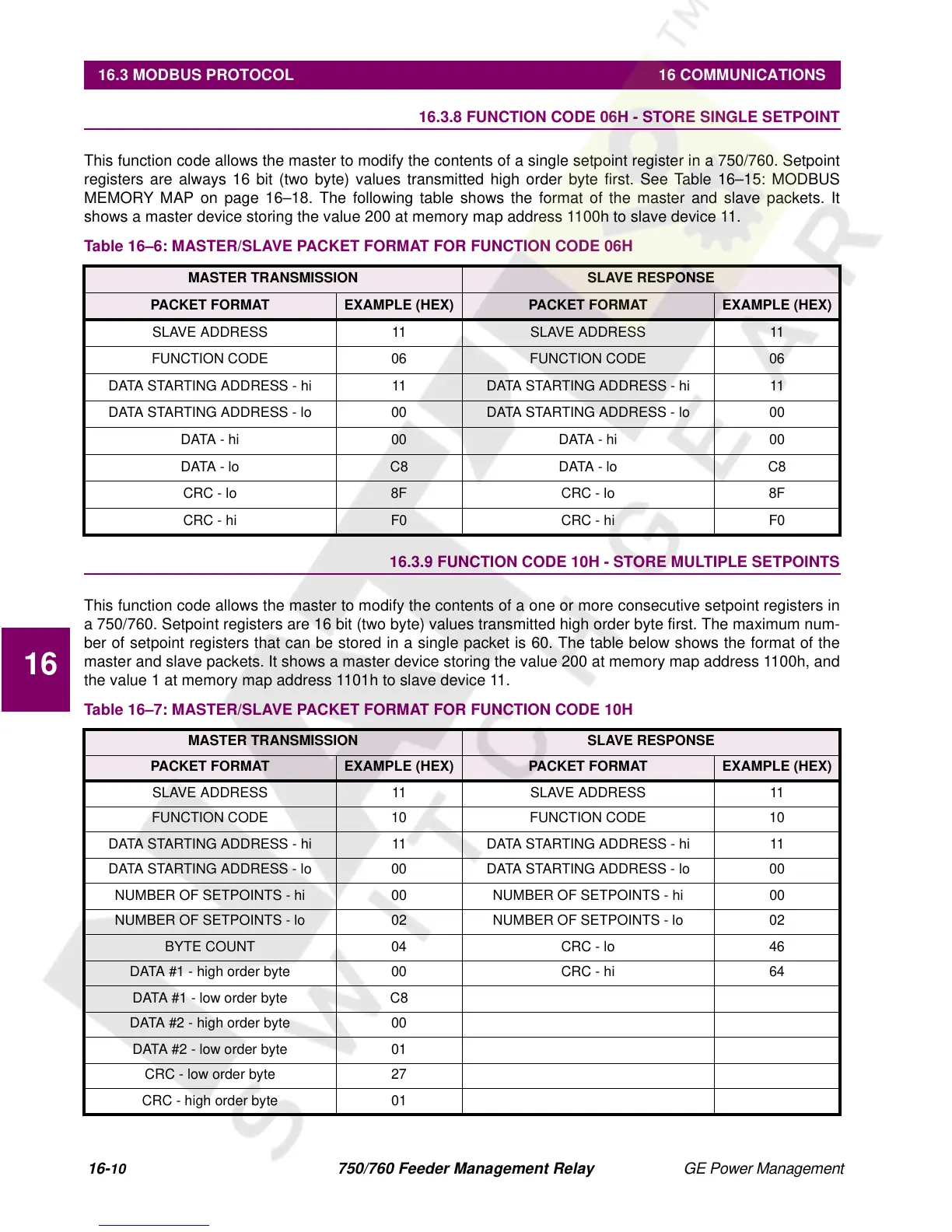
16.3.8 FUNCTION CODE 06H - STORE SINGLE SETPOINT
This function code allows the master to modify the contents of a single setpoint register in a 750/760. Setpoint
registers are always 16 bit (two byte) values transmitted high order byte first. See Table 16–15: MODBUS
MEMORY MAP on page 16–18. The following table shows the format of the master and slave packets. It
shows a master device storing the value 200 at memory map address 1100h to slave device 11.
16.3.9 FUNCTION CODE 10H - STORE MULTIPLE SETPOINTS
This function code allows the master to modify the contents of a one or more consecutive setpoint registers in
a 750/760. Setpoint registers are 16 bit (two byte) values transmitted high order byte first. The maximum num-
ber of setpoint registers that can be stored in a single packet is 60. The table below shows the format of the
master and slave packets. It shows a master device storing the value 200 at memory map address 1100h, and
the value 1 at memory map address 1101h to slave device 11.
Table 16–6: MASTER/SLAVE PACKET FORMAT FOR FUNCTION CODE 06H
MASTER TRANSMISSION SLAVE RESPONSE
PACKET FORMAT EXAMPLE (HEX) PACKET FORMAT EXAMPLE (HEX)
SLAVE ADDRESS 11 SLAVE ADDRESS 11
FUNCTION CODE 06 FUNCTION CODE 06
DATA STARTING ADDRESS - hi 11 DATA STARTING ADDRESS - hi 11
DATA STARTING ADDRESS - lo 00 DATA STARTING ADDRESS - lo 00
DATA - hi 00 DATA - hi 00
DATA - lo C8 DATA - lo C8
CRC - lo 8F CRC - lo 8F
CRC - hi F0 CRC - hi F0
Table 16–7: MASTER/SLAVE PACKET FORMAT FOR FUNCTION CODE 10H
MASTER TRANSMISSION SLAVE RESPONSE
PACKET FORMAT EXAMPLE (HEX) PACKET FORMAT EXAMPLE (HEX)
SLAVE ADDRESS 11 SLAVE ADDRESS 11
FUNCTION CODE 10 FUNCTION CODE 10
DATA STARTING ADDRESS - hi 11 DATA STARTING ADDRESS - hi 11
DATA STARTING ADDRESS - lo 00 DATA STARTING ADDRESS - lo 00
NUMBER OF SETPOINTS - hi 00 NUMBER OF SETPOINTS - hi 00
NUMBER OF SETPOINTS - lo 02 NUMBER OF SETPOINTS - lo 02
BYTE COUNT 04 CRC - lo 46
DATA #1 - high order byte 00 CRC - hi 64
DATA #1 - low order byte C8
DATA #2 - high order byte 00
DATA #2 - low order byte 01
CRC - low order byte 27
CRC - high order byte 01
 Loading...


