GE Power Management 750/760 Feeder Management Relay 6
-
5
6 ACTUAL VALUES 6.2 A1 STATUS
6
6.2.4 LAST TRIP DATA
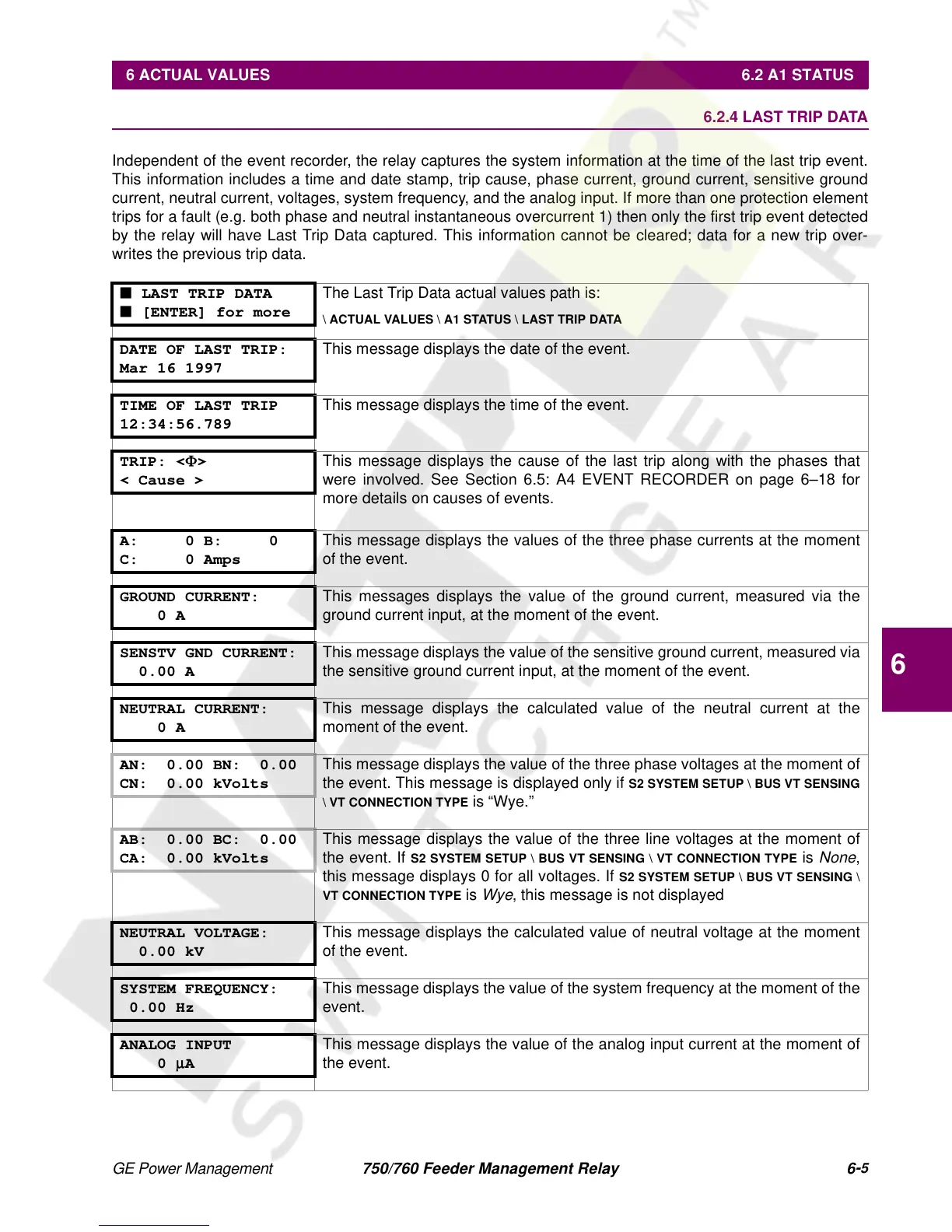
Independent of the event recorder, the relay captures the system information at the time of the last trip event.
This information includes a time and date stamp, trip cause, phase current, ground current, sensitive ground
current, neutral current, voltages, system frequency, and the analog input. If more than one protection element
trips for a fault (e.g. both phase and neutral instantaneous overcurrent 1) then only the first trip event detected
by the relay will have Last Trip Data captured. This information cannot be cleared; data for a new trip over-
writes the previous trip data.
■ LAST TRIP DATA
■ [ENTER] for more
The Last Trip Data actual values path is:
\ ACTUAL VALUES \ A1 STATUS \ LAST TRIP DATA
DATE OF LAST TRIP:
Mar 16 1997
This message displays the date of the event.
TIME OF LAST TRIP
12:34:56.789
This message displays the time of the event.
TRIP: <
Φ
>
< Cause >
This message displays the cause of the last trip along with the phases that
were involved. See Section 6.5: A4 EVENT RECORDER on page 6–18 for
more details on causes of events.
A: 0 B: 0
C: 0 Amps
This message displays the values of the three phase currents at the moment
of the event.
GROUND CURRENT:
0 A
This messages displays the value of the ground current, measured via the
ground current input, at the moment of the event.
SENSTV GND CURRENT:
0.00 A
This message displays the value of the sensitive ground current, measured via
the sensitive ground current input, at the moment of the event.
NEUTRAL CURRENT:
0 A
This message displays the calculated value of the neutral current at the
moment of the event.
AN: 0.00 BN: 0.00
CN: 0.00 kVolts
This message displays the value of the three phase voltages at the moment of
the event. This message is displayed only if
S2 SYSTEM SETUP \ BUS VT SENSING
\ VT CONNECTION TYPE
is “Wye.”
AB: 0.00 BC: 0.00
CA: 0.00 kVolts
This message displays the value of the three line voltages at the moment of
the event. If
S2 SYSTEM SETUP \ BUS VT SENSING \ VT CONNECTION TYPE
is
None
,
this message displays 0 for all voltages. If
S2 SYSTEM SETUP \ BUS VT SENSING \
VT CONNECTION TYPE
is
Wye
, this message is not displayed
NEUTRAL VOLTAGE:
0.00 kV
This message displays the calculated value of neutral voltage at the moment
of the event.
SYSTEM FREQUENCY:
0.00 Hz
This message displays the value of the system frequency at the moment of the
event.
ANALOG INPUT
0
µ
A
This message displays the value of the analog input current at the moment of
the event.
 Loading...


