6-
18
750/760 Feeder Management Relay GE Power Management
6.5 A4 EVENT RECORDER 6 ACTUAL VALUES
6
6.5 A4 EVENT RECORDER 6.5.1 DESCRIPTION
The 750/760 has an event recorder which runs continuously, capturing and storing the last 128 events. All
event recorder information is stored in non-volatile memory so the information is maintained after losing relay
control power.
6.5.2 EVENT RECORDS
The last 128 events are displayed with the newest event first and the oldest event last. Each event has a
header message which contains a summary of the event that occurred. Each event is assigned an event num-
ber equal to the number of events that have occurred since the recorder was cleared; the event number is
incremented for each new event. Event recorder data can be cleared with the
S1 RELAY SETUP \ CLEAR DATA \
CLEAR EVENT RECORDER DATA?
command.
Event information is gathered at the instant the event occurs which means the current and voltage readings
may reflect the transient nature of the event as opposed to steady state values. All messages pertaining to
phase voltages A-N, B-N, and C-N are only displayed if the
VT CONNECTION TYPE
setpoint is programmed to
wye
. If the
VT CONNECTION TYPE
setpoint is programmed to
delta
, line voltages A-B, B-C, and C-A are dis-
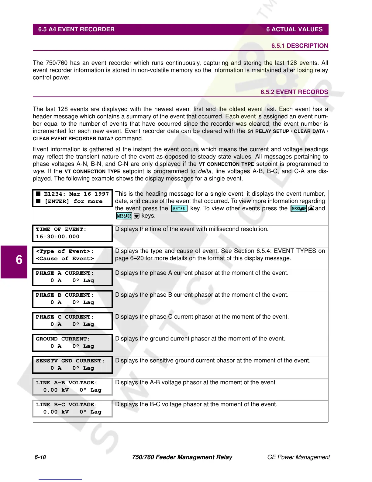
played. The following example shows the display messages for a single event.
■ E1234: Mar 16 1997
■ [ENTER] for more
This is the heading message for a single event; it displays the event number,
date, and cause of the event that occurred. To view more information regarding
the event press the key. To view other events press the and
keys.
TIME OF EVENT:
16:30:00.000
Displays the time of the event with millisecond resolution.
<Type of Event>:
<Cause of Event>
Displays the type and cause of event. See Section 6.5.4: EVENT TYPES on
page 6–20 for more details on the format of this display message.
PHASE A CURRENT:
0 A 0° Lag
Displays the phase A current phasor at the moment of the event.
PHASE B CURRENT:
0 A 0° Lag
Displays the phase B current phasor at the moment of the event.
PHASE C CURRENT:
0 A 0° Lag
Displays the phase C current phasor at the moment of the event.
GROUND CURRENT:
0 A 0° Lag
Displays the ground current phasor at the moment of the event.
SENSTV GND CURRENT:
0 A 0° Lag
Displays the sensitive ground current phasor at the moment of the event.
LINE A-B VOLTAGE:
0.00 kV 0° Lag
Displays the A-B voltage phasor at the moment of the event.
LINE B-C VOLTAGE:
0.00 kV 0° Lag
Displays the B-C voltage phasor at the moment of the event.
ENTER
 Loading...


