GE Power Management 750/760 Feeder Management Relay 12-
1
12 S5 PROTECTION 12.1 TIME OVERCURRENT CURVE CHARACTERISTICS
12
12 S5 PROTECTION 12.1 TIME OVERCURRENT CURVE CHARACTERISTICS 12.1.1 DESCRIPTION
The relay has a total of six phase, two neutral, one ground, one sensitive ground, and one negative sequence
time overcurrent elements. The programming of the time-current characteristics of these elements is identical
in all cases and will only be covered in this general section. The required curve is established by programming
a Pickup Current, Curve Shape, Curve Multiplier, and Reset Time. The Curve Shape can be either a standard
shape or a user-defined shape programmed with the FlexCurve™ feature.
Accurate coordination may require changing the time overcurrent characteristics of particular elements under
different conditions. For manual closing or picking up a cold load, a different time-current characteristic can be
produced by increasing the pickup current setting. In the 760, the pickup current can also be raised between
autoreclose shots. The following setpoints are used to program the time-current characteristics.
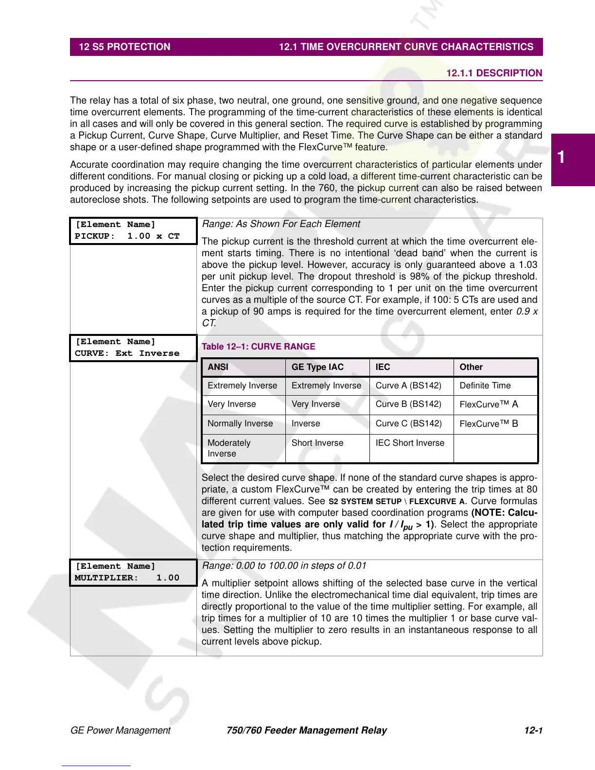
[Element Name]
PICKUP: 1.00 x CT
Range: As Shown For Each Element
The pickup current is the threshold current at which the time overcurrent ele-
ment starts timing. There is no intentional ‘dead band’ when the current is
above the pickup level. However, accuracy is only guaranteed above a 1.03
per unit pickup level. The dropout threshold is 98% of the pickup threshold.
Enter the pickup current corresponding to 1 per unit on the time overcurrent
curves as a multiple of the source CT. For example, if 100: 5 CTs are used and
a pickup of 90 amps is required for the time overcurrent element, enter
0.9 x
CT
.
[Element Name]
CURVE: Ext Inverse
Select the desired curve shape. If none of the standard curve shapes is appro-
priate, a custom FlexCurve™ can be created by entering the trip times at 80
different current values. See
S2 SYSTEM SETUP \ FLEXCURVE A
. Curve formulas
are given for use with computer based coordination programs
(NOTE: Calcu-
lated trip time values are only valid for
I/I
pu
> 1)
. Select the appropriate
curve shape and multiplier, thus matching the appropriate curve with the pro-
tection requirements.
[Element Name]
MULTIPLIER: 1.00
Range: 0.00 to 100.00 in steps of 0.01
A multiplier setpoint allows shifting of the selected base curve in the vertical
time direction. Unlike the electromechanical time dial equivalent, trip times are
directly proportional to the value of the time multiplier setting. For example, all
trip times for a multiplier of 10 are 10 times the multiplier 1 or base curve val-
ues. Setting the multiplier to zero results in an instantaneous response to all
current levels above pickup.
 Loading...


