8-
6
750/760 Feeder Management Relay GE Power Management
8.6 TRACE MEMORY 8 S1 RELAY SETUP
8
8.6 TRACE MEMORY 8.6.1 DESCRIPTION
The waveform capture feature is similar to a transient / fault recorder. It captures oscillography / waveform data
in response to a variety of system events. Data is captured for the analog current and voltage inputs (
I
a
,
I
b
,
I
c
,
I
g
,
I
sg
,
V
a
,
V
b
,
V
c
,
V
s
) as well as digital data for the output relays and input contact states. The trace memory
data can be downloaded to the 750/760 PC Program for display and diagnostics purposes. All data is stored in
volatile RAM memory which means that the information is lost when power to the relay is lost. The amount of
data to capture and the trigger point are configurable as described below.
8.6.2 SETTINGS
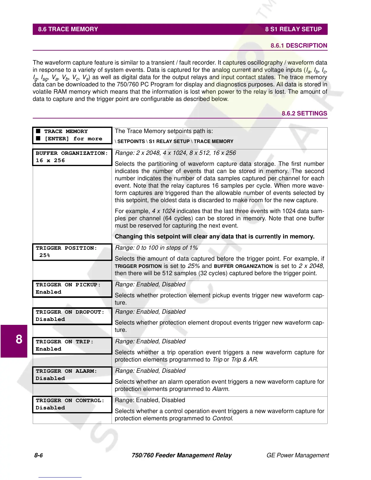
■ TRACE MEMORY
■ [ENTER] for more
The Trace Memory setpoints path is:
\ SETPOINTS \ S1 RELAY SETUP \ TRACE MEMORY
BUFFER ORGANIZATION:
16 x 256
Range: 2 x 2048, 4 x 1024, 8 x 512, 16 x 256
Selects the partitioning of waveform capture data storage. The first number
indicates the number of events that can be stored in memory. The second
number indicates the number of data samples captured per channel for each
event. Note that the relay captures 16 samples per cycle. When more wave-
form captures are triggered than the allowable number of events selected by
this setpoint, the oldest data is discarded to make room for the new capture.
For example,
4 x 1024
indicates that the last three events with 1024 data sam-
ples per channel (64 cycles) can be stored in memory. Note that one buffer
must be reserved for capturing the next event.
Changing this setpoint will clear any data that is currently in memory.
TRIGGER POSITION:
25%
Range: 0 to 100 in steps of 1%
Selects the amount of data captured before the trigger point. For example, if
TRIGGER POSITION
is set to
25%
and
BUFFER ORGANIZATION
is set to
2 x 2048
,
then there will be 512 samples (32 cycles) captured before the trigger point.
TRIGGER ON PICKUP:
Enabled
Range: Enabled, Disabled
Selects whether protection element pickup events trigger new waveform cap-
ture.
TRIGGER ON DROPOUT:
Disabled
Range: Enabled, Disabled
Selects whether protection element dropout events trigger new waveform cap-
ture.
TRIGGER ON TRIP:
Enabled
Range: Enabled, Disabled
Selects whether a trip operation event triggers a new waveform capture for
protection elements programmed to
Trip
or
Trip & AR
.
TRIGGER ON ALARM:
Disabled
Range: Enabled, Disabled
Selects whether an alarm operation event triggers a new waveform capture for
protection elements programmed to
Alarm
.
TRIGGER ON CONTROL:
Disabled
Range: Enabled, Disabled
Selects whether a control operation event triggers a new waveform capture for
protection elements programmed to
Control
.
 Loading...


