GE Power Management 750/760 Feeder Management Relay 3-
11
3 INSTALLATION 3.2 TYPICAL WIRING
3
3.2.8 ZERO SEQUENCE CT INSTALLATION
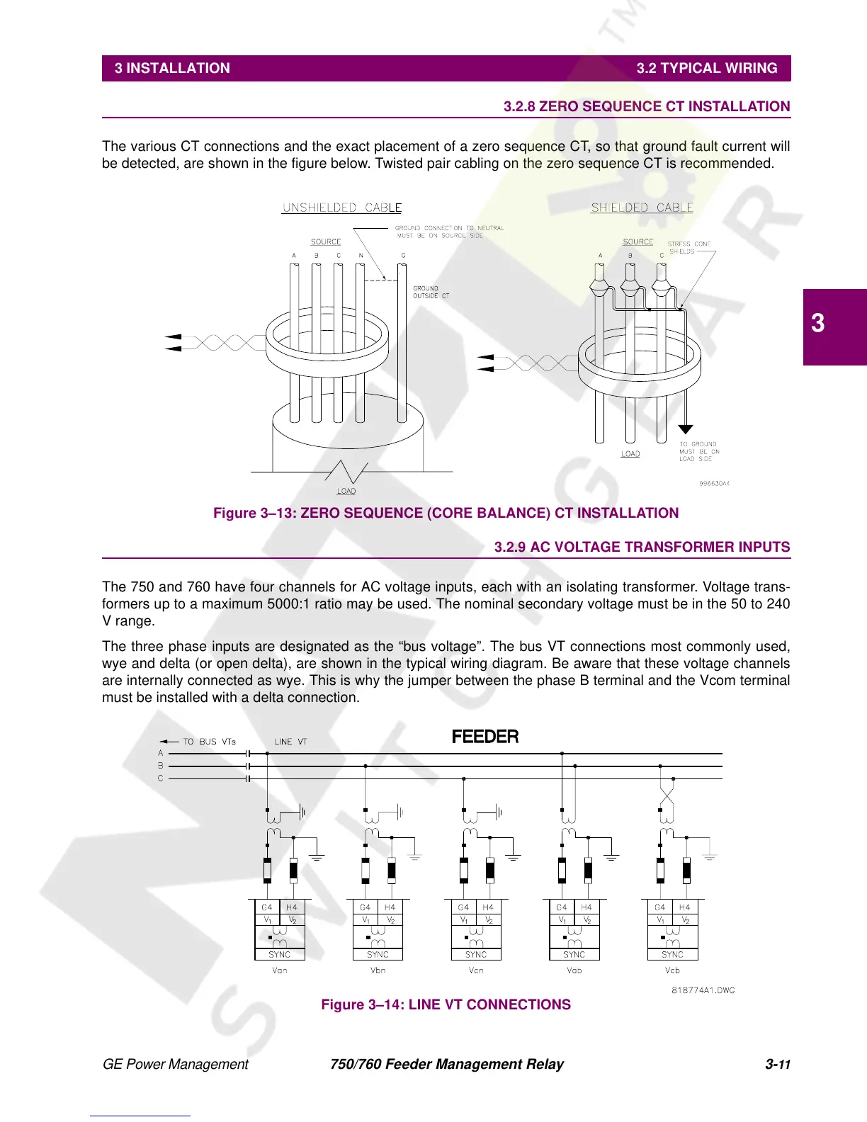
The various CT connections and the exact placement of a zero sequence CT, so that ground fault current will
be detected, are shown in the figure below. Twisted pair cabling on the zero sequence CT is recommended.
Figure 3–13: ZERO SEQUENCE (CORE BALANCE) CT INSTALLATION
3.2.9 AC VOLTAGE TRANSFORMER INPUTS
The 750 and 760 have four channels for AC voltage inputs, each with an isolating transformer. Voltage trans-
formers up to a maximum 5000:1 ratio may be used. The nominal secondary voltage must be in the 50 to 240
V range.
The three phase inputs are designated as the “bus voltage”. The bus VT connections most commonly used,
wye and delta (or open delta), are shown in the typical wiring diagram. Be aware that these voltage channels
are internally connected as wye. This is why the jumper between the phase B terminal and the Vcom terminal
must be installed with a delta connection.
Figure 3–14: LINE VT CONNECTIONS
 Loading...


