6-
10
750/760 Feeder Management Relay GE Power Management
6.3 A2 METERING 6 ACTUAL VALUES
6
6.3.4 FREQUENCY
Frequency is measured with a zero-crossing detector from the Va voltage. Frequency and frequency decay will
read zero if the potential across the Va input terminals is less than 10 Volts.
6.3.5 SYNCHRONIZING VOLTAGE
The voltage magnitude, phase angle, frequency, and delta values for the line VT synchronizing voltage input
are displayed as shown below.
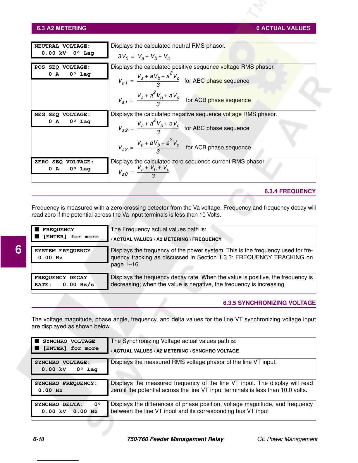
NEUTRAL VOLTAGE:
0.00 kV 0° Lag
Displays the calculated neutral RMS phasor.
POS SEQ VOLTAGE:
0 A 0° Lag
Displays the calculated positive sequence voltage RMS phasor.
NEG SEQ VOLTAGE:
0 A 0° Lag
Displays the calculated negative sequence voltage RMS phasor.
ZERO SEQ VOLTAGE:
0 A 0° Lag
Displays the calculated zero sequence current RMS phasor.
■ FREQUENCY
■ [ENTER] for more
The Frequency actual values path is:
\ ACTUAL VALUES \ A2 METERING \ FREQUENCY
SYSTEM FREQUENCY
0.00 Hz
Displays the frequency of the power system. This is the frequency used for fre-
quency tracking as discussed in Section 1.3.3: FREQUENCY TRACKING on
page 1–16.
FREQUENCY DECAY
RATE: 0.00 Hz/s
Displays the frequency decay rate. When the value is positive, the frequency is
decreasing; when the value is negative, the frequency is increasing.
■ SYNCHRO VOLTAGE
■ [ENTER] for more
The Synchronizing Voltage actual values path is:
\ ACTUAL VALUES \ A2 METERING \ SYNCHRO VOLTAGE
SYNCHRO VOLTAGE:
0.00 kV 0° Lag
Displays the measured RMS voltage phasor of the line VT input.
SYNCHRO FREQUENCY:
0.00 Hz
Displays the measured frequency of the line VT input. The display will read
zero if the potential across the line VT input terminals is less than 10.0 volts.
SYNCHRO DELTA: 0°
0.00 kV 0.00 Hz
Displays the differences of phase position, voltage magnitude, and frequency
between the line VT input and its corresponding bus VT input
3V
0
V
a
V
b
V
c
++=
V
a1
V
a
aV
b
a
2
V
c
++
3
------------------------------------------- for ABC phase sequence =
V
a1
V
a
a
2
V
b
aV
c
++
3
------------------------------------------- for ACB phase sequence=
V
a2
V
a
a
2
V
b
aV
c
++
3
------------------------------------------- for ABC phase sequence =
V
a2
V
a
aV
b
a
2
V
c
++
3
-------------------------------------------
for ACB phase sequence=
V
a0
V
a
V
b
V
c
++
3
---------------------------------=
 Loading...


