GE Power Management 750/760 Feeder Management Relay 9-
1
9 S2 SYSTEM SETUP 9.1 CURRENT SENSING
9
9 S2 SYSTEM SETUP 9.1 CURRENT SENSING 9.1.1 DESCRIPTION
This group of setpoints is critical for all overcurrent protection features that have settings specified in multiples
of CT rating. When the relay is ordered, the phase, ground, and sensitive ground CT inputs must be specified
as either 1 Amp or 5 Amp.
As the phase CTs are connected in wye (star), the calculated phasor sum of the three phase currents (
I
a
+
I
b
+
I
c
= Neutral Current = 3
I
0
) is used as the input for the neutral overcurrent. In addition, a zero-sequence (core
balance) CT which senses current in all of the circuit primary conductors, or a CT in a neutral grounding con-
ductor may also be used. For this configuration, the ground CT primary rating must be entered. To detect low
level ground fault currents, the sensitive ground input may be used. In this case, the sensitive ground CT pri-
mary rating must be entered. For additional details on CT connections, refer to Section 3.2: TYPICAL WIRING
on page 3–5.
9.1.2 SETTINGS
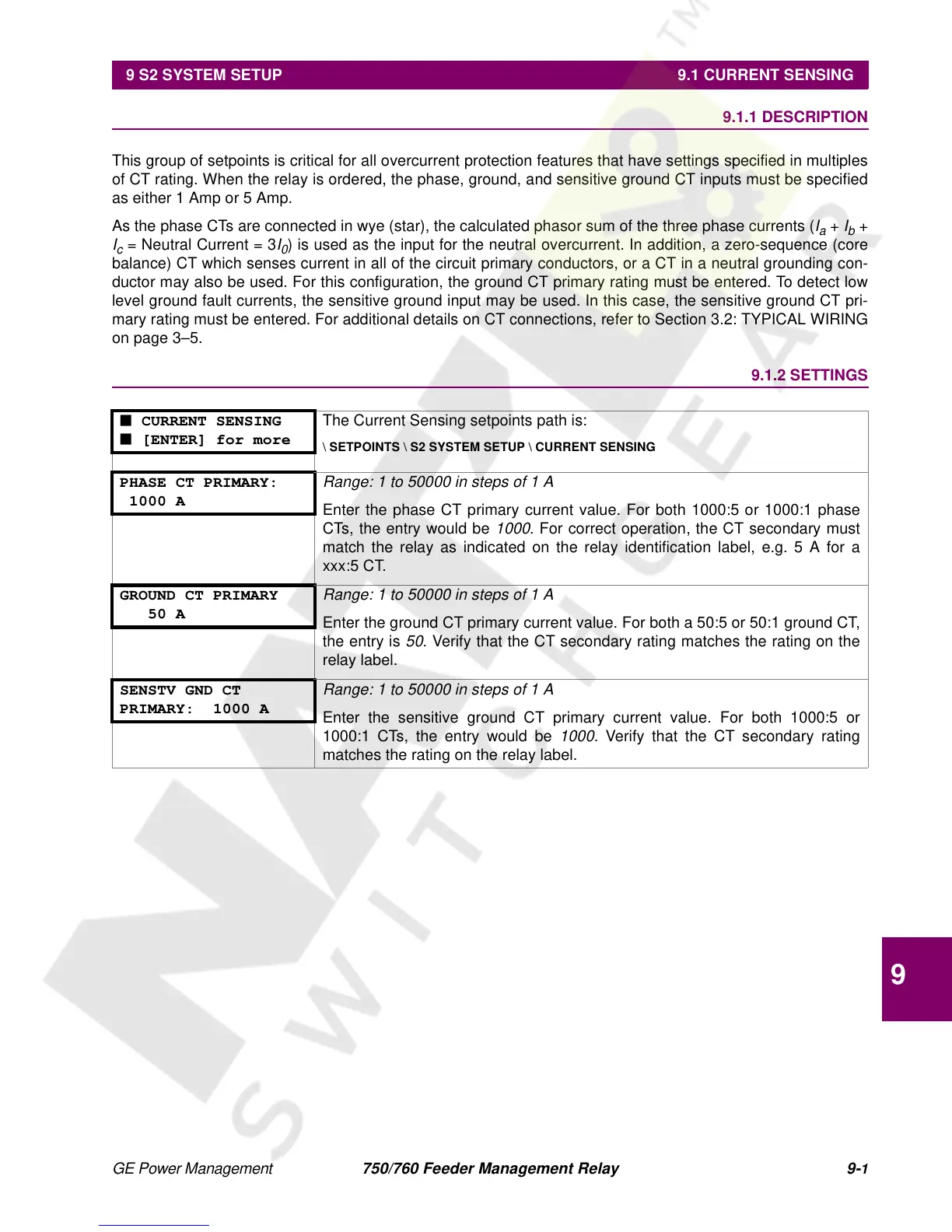
■ CURRENT SENSING
■ [ENTER] for more
The Current Sensing setpoints path is:
\ SETPOINTS \ S2 SYSTEM SETUP \ CURRENT SENSING
PHASE CT PRIMARY:
1000 A
Range: 1 to 50000 in steps of 1 A
Enter the phase CT primary current value. For both 1000:5 or 1000:1 phase
CTs, the entry would be
1000
. For correct operation, the CT secondary must
match the relay as indicated on the relay identification label, e.g. 5 A for a
xxx:5 CT.
GROUND CT PRIMARY
50 A
Range: 1 to 50000 in steps of 1 A
Enter the ground CT primary current value. For both a 50:5 or 50:1 ground CT,
the entry is
50
. Verify that the CT secondary rating matches the rating on the
relay label.
SENSTV GND CT
PRIMARY: 1000 A
Range: 1 to 50000 in steps of 1 A
Enter the sensitive ground CT primary current value. For both 1000:5 or
1000:1 CTs, the entry would be
1000
. Verify that the CT secondary rating
matches the rating on the relay label.
 Loading...


