12-
56
750/760 Feeder Management Relay GE Power Management
12.7 VOLTAGE 12 S5 PROTECTION
12
12.7.6 NEUTRAL DISPLACEMENT
The 750/760 incorporates a Neutral Displacement element, which uses the internally derived 3
V
o
value. This
protection element requires the three phase Bus VTs to be wye connected. When setting the pickup level for
this element, it is important to consider the error in the VT ratio as well as the normal voltage unbalance on the
system. The Neutral Displacement setpoints are as follows.
†
NOTE: The same curves used for the time overcurrent elements are used for Neutral Displacement. When
using the curve to determine the operating time of the Neutral Displacement element, substitute the ratio of
neutral voltage to the pickup level for the current ratio shown on the horizontal axis of the curve plot.
The user should be aware that the neutral displacement feature should be applied with caution. It would nor-
mally be applied to give line to ground fault coverage on high impedance grounded or ungrounded systems,
which are isolated. This constraint stems from the fact that a measurement of 3
V
0
cannot discriminate between
a faulted circuit and an adjacent healthy circuit. Use of a time delayed back-up or an alarm mode allow other
protections an opportunity to isolate the faulted element first.
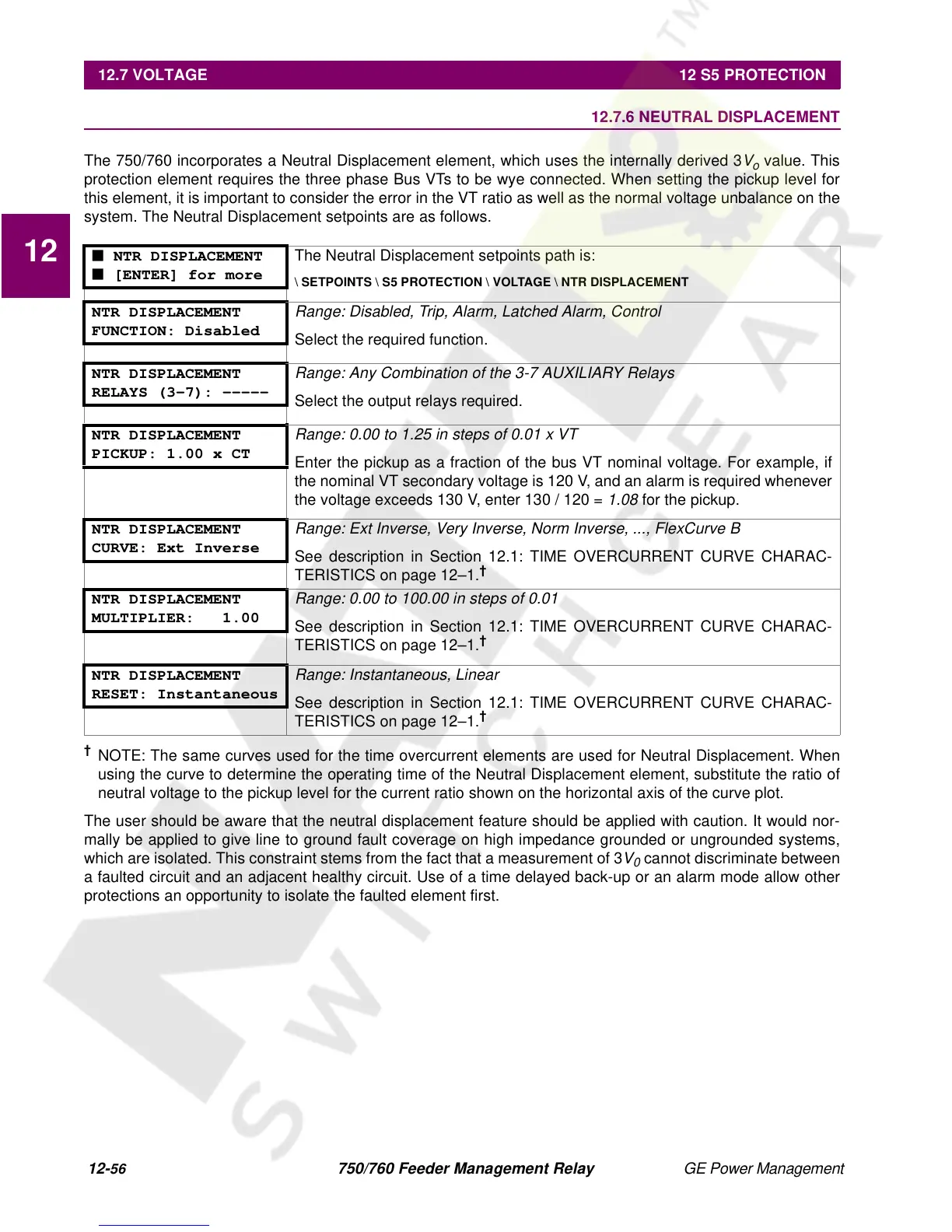
■ NTR DISPLACEMENT
■ [ENTER] for more
The Neutral Displacement setpoints path is:
\ SETPOINTS \ S5 PROTECTION \ VOLTAGE \ NTR DISPLACEMENT
NTR DISPLACEMENT
FUNCTION: Disabled
Range: Disabled, Trip, Alarm, Latched Alarm, Control
Select the required function.
NTR DISPLACEMENT
RELAYS (3-7): -----
Range: Any Combination of the 3-7 AUXILIARY Relays
Select the output relays required.
NTR DISPLACEMENT
PICKUP: 1.00 x CT
Range: 0.00 to 1.25 in steps of 0.01 x VT
Enter the pickup as a fraction of the bus VT nominal voltage. For example, if
the nominal VT secondary voltage is 120 V, and an alarm is required whenever
the voltage exceeds 130 V, enter 130 / 120 =
1.08
for the pickup.
NTR DISPLACEMENT
CURVE: Ext Inverse
Range: Ext Inverse, Very Inverse, Norm Inverse, ..., FlexCurve B
See description in Section 12.1: TIME OVERCURRENT CURVE CHARAC-
TERISTICS on page 12–1.
†
NTR DISPLACEMENT
MULTIPLIER: 1.00
Range: 0.00 to 100.00 in steps of 0.01
See description in Section 12.1: TIME OVERCURRENT CURVE CHARAC-
TERISTICS on page 12–1.
†
NTR DISPLACEMENT
RESET: Instantaneous
Range: Instantaneous, Linear
See description in Section 12.1: TIME OVERCURRENT CURVE CHARAC-
TERISTICS on page 12–1.
†
 Loading...


