GE Power Management 750/760 Feeder Management Relay 12-
39
12 S5 PROTECTION 12.5 SENSITIVE GROUND CURRENT
12
d) CALCULATING THE STABILIZING RESISTOR
Assume
I
PICKUP
to be 30% rated transformer current, that is:
This means also (assuming 1% for CT magnetizing current):
and therefore:
e) DETERMINING THE USE OF A NON-LINEAR RESISTOR
We have:
A non-linear resistor is recommended as the peak fault voltage is above relay voltage maximum of 2000 V.
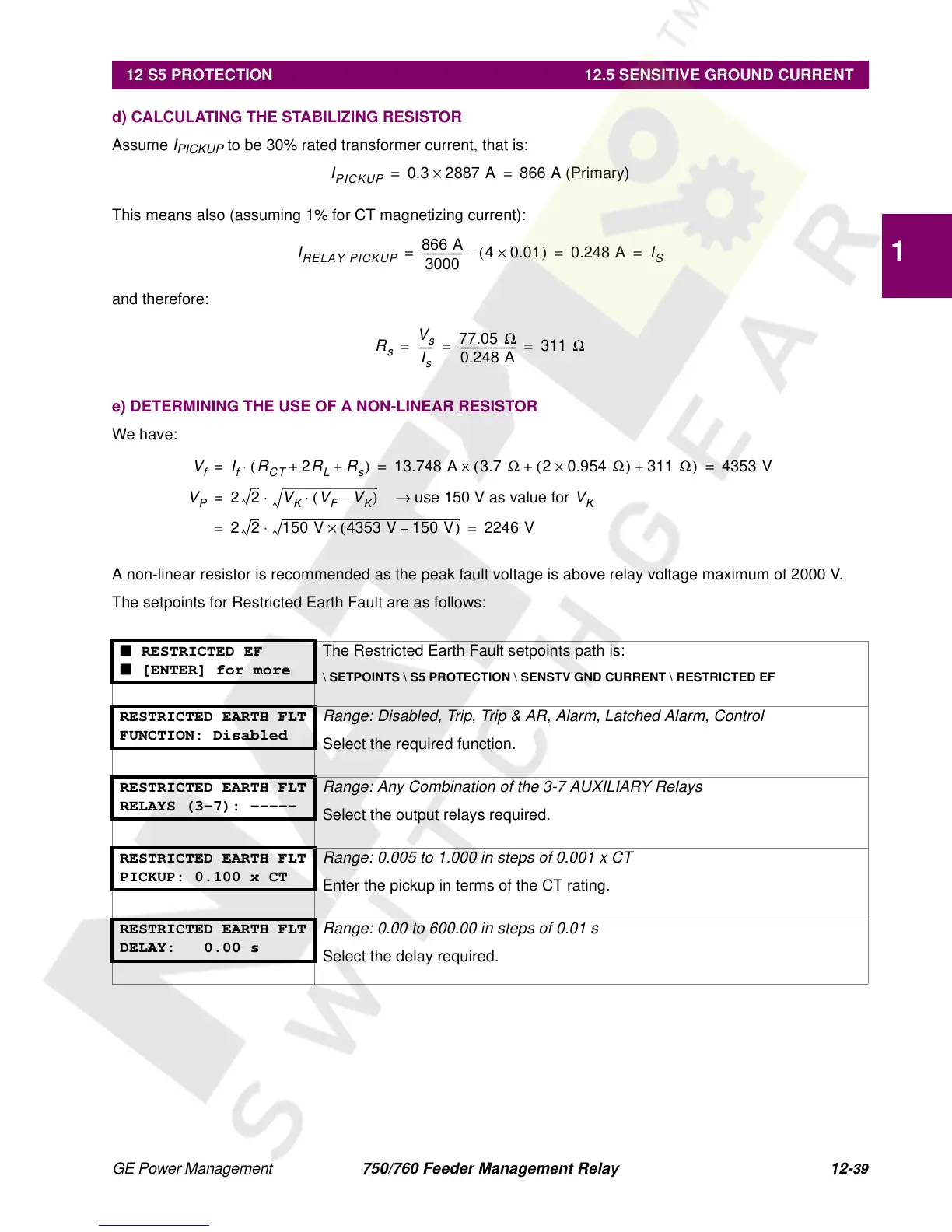
The setpoints for Restricted Earth Fault are as follows:
■ RESTRICTED EF
■ [ENTER] for more
The Restricted Earth Fault setpoints path is:
\ SETPOINTS \ S5 PROTECTION \ SENSTV GND CURRENT \ RESTRICTED EF
RESTRICTED EARTH FLT
FUNCTION: Disabled
Range: Disabled, Trip, Trip & AR, Alarm, Latched Alarm, Control
Select the required function.
RESTRICTED EARTH FLT
RELAYS (3-7): -----
Range: Any Combination of the 3-7 AUXILIARY Relays
Select the output relays required.
RESTRICTED EARTH FLT
PICKUP: 0.100 x CT
Range: 0.005 to 1.000 in steps of 0.001 x CT
Enter the pickup in terms of the CT rating.
RESTRICTED EARTH FLT
DELAY: 0.00 s
Range: 0.00 to 600.00 in steps of 0.01 s
Select the delay required.
I
PICKUP
0.3 2887 A
×
866 A (Primary)==
I
RELAY
PICKUP
866 A
3000
----------------
40.01
×()
– 0.248 A
I
S
===
R
s
V
s
I
s
------
77.05
Ω
0.248 A
----------------------
311
Ω
== =
V
f
I
f
R
CT
2
R
L
R
s
++
()⋅
13.748 A 3.7
Ω
20.954
Ω×()
311
Ω
++
()×
4353 V== =
V
P
22
V
K
V
F
V
K
–
()⋅
use 150 V as value for
→
V
K
⋅
=
2 2 150 V 4353 V 150 V–
()×⋅
2246 V==
 Loading...


