4-
8
750/760 Feeder Management Relay GE Power Management
4.4 USING 750/760 PC 4 750/760 PC PROGRAM
4
5. The 750/760 PC Program will automatically list file names ending with
*.000
Click on the appropriate file
name such that it appears in the
File Name
box. Click on
OK
to continue.
6. A similar dialog box as in step 3 will appear asking for the control board firmware file. Locate this file and
click on
OK
to continue.
7. Another warning message will appear to ensure you want to continue. Click on the
Y
es
button to continue.
8. Upon completion, the program will put the relay back to “normal mode”.
9. The setpoint file saved in step 1 can now be loaded into the relay. (see Section 4.4.6: LOADING SET-
POINTS FROM A FILE on page 4–10).
4.4.3 ENTERING SETPOINTS
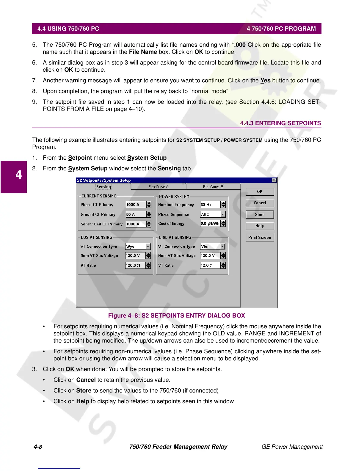
The following example illustrates entering setpoints for
S2 SYSTEM SETUP / POWER SYSTEM
using the 750/760 PC
Program.
1. From the
S
etpoint
menu select
System Setup
2. From the
S
ystem Setup
window select the
Sensing
tab.
Figure 4–8: S2 SETPOINTS ENTRY DIALOG BOX
• For setpoints requiring numerical values (i.e. Nominal Frequency) click the mouse anywhere inside the
setpoint box. This displays a numerical keypad showing the OLD value, RANGE and INCREMENT of
the setpoint being modified. The up/down arrows can also be used to increment/decrement the value.
• For setpoints requiring non-numerical values (i.e. Phase Sequence) clicking anywhere inside the set-
point box or using the down arrow will cause a selection menu to be displayed.
3. Click on
OK
when done. You will be prompted to store the setpoints.
•Click on
Cancel
to retain the previous value.
•Click on
Store
to send the values to the 750/760 (if connected)
•Click on
Help
to display help related to setpoints seen in this window
 Loading...


