GE Power Management 750/760 Feeder Management Relay 12-
13
12 S5 PROTECTION 12.2 DIRECTIONAL OVERCURRENT CHARACTERISTICS
12
12.2.5 PHASE DIRECTIONAL
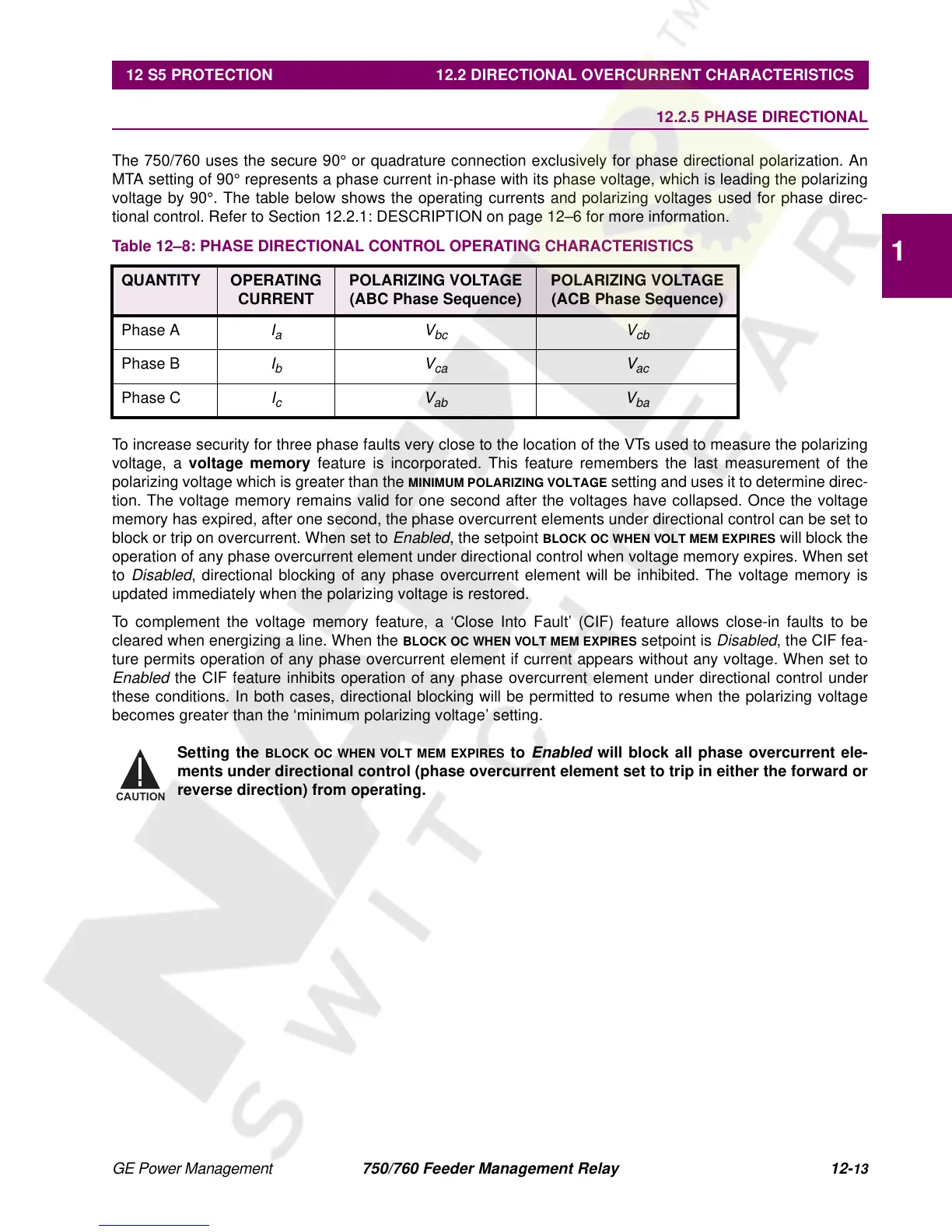
The 750/760 uses the secure 90° or quadrature connection exclusively for phase directional polarization. An
MTA setting of 90° represents a phase current in-phase with its phase voltage, which is leading the polarizing
voltage by 90°. The table below shows the operating currents and polarizing voltages used for phase direc-
tional control. Refer to Section 12.2.1: DESCRIPTION on page 12–6 for more information.
To increase security for three phase faults very close to the location of the VTs used to measure the polarizing
voltage, a
voltage memory
feature is incorporated. This feature remembers the last measurement of the
polarizing voltage which is greater than the
MINIMUM POLARIZING VOLTAGE
setting and uses it to determine direc-
tion. The voltage memory remains valid for one second after the voltages have collapsed. Once the voltage
memory has expired, after one second, the phase overcurrent elements under directional control can be set to
block or trip on overcurrent. When set to
Enabled
, the setpoint
BLOCK OC WHEN VOLT MEM EXPIRES
will block the
operation of any phase overcurrent element under directional control when voltage memory expires. When set
to
Disabled
, directional blocking of any phase overcurrent element will be inhibited. The voltage memory is
updated immediately when the polarizing voltage is restored.
To complement the voltage memory feature, a ‘Close Into Fault’ (CIF) feature allows close-in faults to be
cleared when energizing a line. When the
BLOCK OC WHEN VOLT MEM EXPIRES
setpoint is
Disabled
, the CIF fea-
ture permits operation of any phase overcurrent element if current appears without any voltage. When set to
Enabled
the CIF feature inhibits operation of any phase overcurrent element under directional control under
these conditions. In both cases, directional blocking will be permitted to resume when the polarizing voltage
becomes greater than the ‘minimum polarizing voltage’ setting.
Setting the
BLOCK OC WHEN VOLT MEM EXPIRES
to
Enabled
will block all phase overcurrent ele-
ments under directional control (phase overcurrent element set to trip in either the forward or
reverse direction) from operating.
Table 12–8: PHASE DIRECTIONAL CONTROL OPERATING CHARACTERISTICS
QUANTITY OPERATING
CURRENT
POLARIZING VOLTAGE
(ABC Phase Sequence)
POLARIZING VOLTAGE
(ACB Phase Sequence)
Phase A
I
a
V
bc
V
cb
Phase B
I
b
V
ca
V
ac
Phase C
I
c
V
ab
V
ba
CAUTION
 Loading...


