10-
4
750/760 Feeder Management Relay GE Power Management
10.3 BREAKER FUNCTIONS 10 S3 LOGIC INPUTS
10
10.3 BREAKER FUNCTIONS 10.3.1 DESCRIPTION
The following logic functions are used to determine whether the circuit breaker is open, closed, or discon-
nected from the main power circuit, as monitored by auxiliary contacts on a drawout breaker racking mecha-
nism, or on the associated isolating disconnect switches on a fixed circuit breaker.
If neither the 52a or 52b contacts are installed then the following functions cannot be performed:
1. It is strongly recommended that the Breaker Operation Failure alarm be enabled when
either 52a or 52b breaker auxiliary contacts are installed.
2. Breaker logic functions must be assigned to logic inputs 1 to 14 as they must only be
contacts.
10.3.2 SETTINGS
For further information regarding operation with only one auxiliary breaker contact, see Section 5.2.3: SYS-
TEM STATUS INDICATORS on page 5–2.
• Monitoring of breaker position
• Breaker Operation Failure
• Feedback control of 1 TRIP and 2 CLOSE relays
• Trip / Close Coil Supervision Without Permissive
• Manual close feature blocking
• Autoreclose
•Transfer
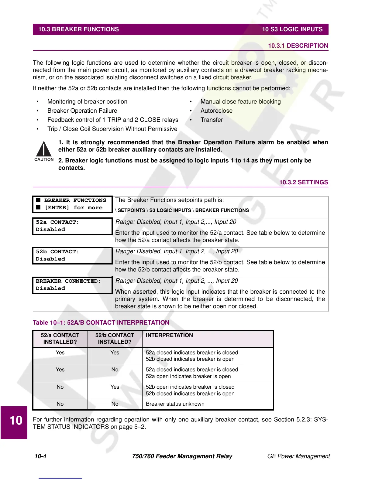
■ BREAKER FUNCTIONS
■ [ENTER] for more
The Breaker Functions setpoints path is:
\ SETPOINTS \ S3 LOGIC INPUTS \ BREAKER FUNCTIONS
52a CONTACT:
Disabled
Range: Disabled, Input 1, Input 2,..., Input 20
Enter the input used to monitor the 52/a contact. See table below to determine
how the 52/a contact affects the breaker state.
52b CONTACT:
Disabled
Range: Disabled, Input 1, Input 2, ..., Input 20
Enter the input used to monitor the 52/b contact. See table below to determine
how the 52/b contact affects the breaker state.
BREAKER CONNECTED:
Disabled
Range: Disabled, Input 1, Input 2, ..., Input 20
When asserted, this logic input indicates that the breaker is connected to the
primary system. When the breaker is determined to be disconnected, the
breaker state is shown to be neither open nor closed.
Table 10–1: 52A/B CONTACT INTERPRETATION
52/a CONTACT
INSTALLED?
52/b CONTACT
INSTALLED?
INTERPRETATION
Yes Yes 52a closed indicates breaker is closed
52b closed indicates breaker is open
Yes No 52a closed indicates breaker is closed
52a open indicates breaker is open
No Yes 52b open indicates breaker is closed
52b closed indicates breaker is open
No No Breaker status unknown
CAUTION
 Loading...


