GE Power Management 750/760 Feeder Management Relay 17-
29
17 COMMISSIONING 17.7 PROTECTION SCHEMES
17
b) FORWARD TRIPPING W/ CURRENT POLARIZATION
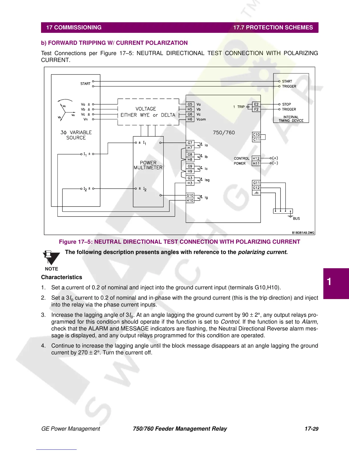
Test Connections per Figure 17–5: NEUTRAL DIRECTIONAL TEST CONNECTION WITH POLARIZING
CURRENT.
Figure 17–5: NEUTRAL DIRECTIONAL TEST CONNECTION WITH POLARIZING CURRENT
The following description presents angles with reference to the
polarizing current
.
Characteristics
1. Set a current of 0.2 of nominal and inject into the ground current input (terminals G10,H10).
2. Set a 3
I
o
current to 0.2 of nominal and in-phase with the ground current (this is the trip direction) and inject
into the relay via the phase current inputs.
3. Increase the lagging angle of 3
I
o
. At an angle lagging the ground current by 90
±
2
°
, any output relays pro-
grammed for this condition should operate if the function is set to
Control
. If the function is set to
Alarm
,
check that the ALARM and MESSAGE indicators are flashing, the Neutral Directional Reverse alarm mes-
sage is displayed, and any output relays programmed for this condition are operated.
4. Continue to increase the lagging angle until the block message disappears at an angle lagging the ground
current by 270
±
2
°
. Turn the current off.
NOTE
 Loading...


