GE Power Management 750/760 Feeder Management Relay 4-
11
4 750/760 PC PROGRAM 4.4 USING 750/760 PC
4
4.4.7 USER MAP
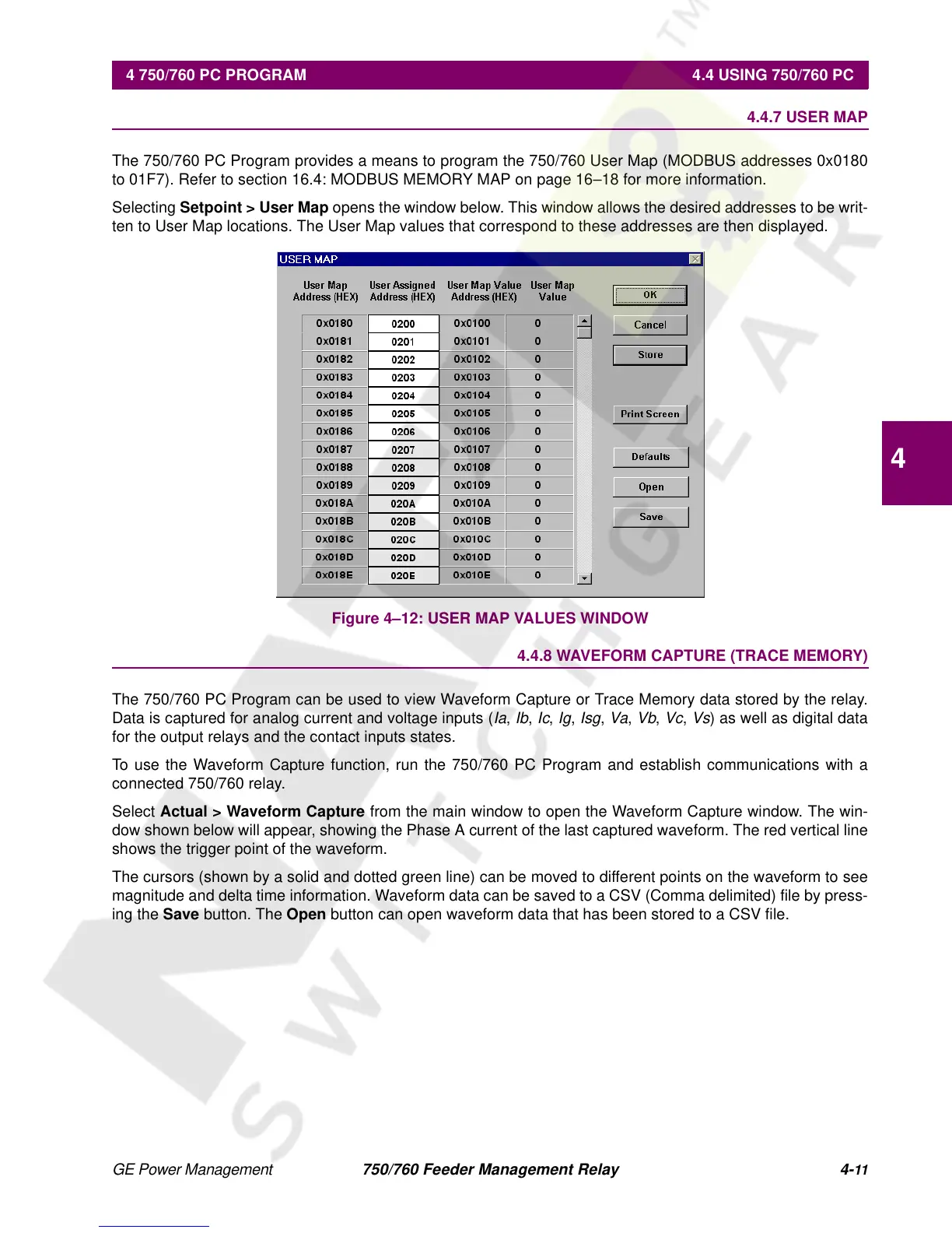
The 750/760 PC Program provides a means to program the 750/760 User Map (MODBUS addresses 0x0180
to 01F7). Refer to section 16.4: MODBUS MEMORY MAP on page 16–18 for more information.
Selecting
Setpoint > User Map
opens the window below. This window allows the desired addresses to be writ-
ten to User Map locations. The User Map values that correspond to these addresses are then displayed.
Figure 4–12: USER MAP VALUES WINDOW
4.4.8 WAVEFORM CAPTURE (TRACE MEMORY)
The 750/760 PC Program can be used to view Waveform Capture or Trace Memory data stored by the relay.
Data is captured for analog current and voltage inputs (
Ia
,
Ib
,
Ic
,
Ig
,
Isg
,
Va
,
Vb
,
Vc
,
Vs
) as well as digital data
for the output relays and the contact inputs states.
To use the Waveform Capture function, run the 750/760 PC Program and establish communications with a
connected 750/760 relay.
Select
Actual > Waveform Capture
from the main window to open the Waveform Capture window. The win-
dow shown below will appear, showing the Phase A current of the last captured waveform. The red vertical line
shows the trigger point of the waveform.
The cursors (shown by a solid and dotted green line) can be moved to different points on the waveform to see
magnitude and delta time information. Waveform data can be saved to a CSV (Comma delimited) file by press-
ing the
Save
button. The
Open
button can open waveform data that has been stored to a CSV file.
 Loading...


