13-
24
750/760 Feeder Management Relay GE Power Management
13.6 ANALOG OUTPUTS 13 S6 MONITORING
13
13.6 ANALOG OUTPUTS 13.6.1 DESCRIPTION
The following setpoints are repeated for
ANALOG OUTPUT 1
through
ANALOG OUTPUT 8
.
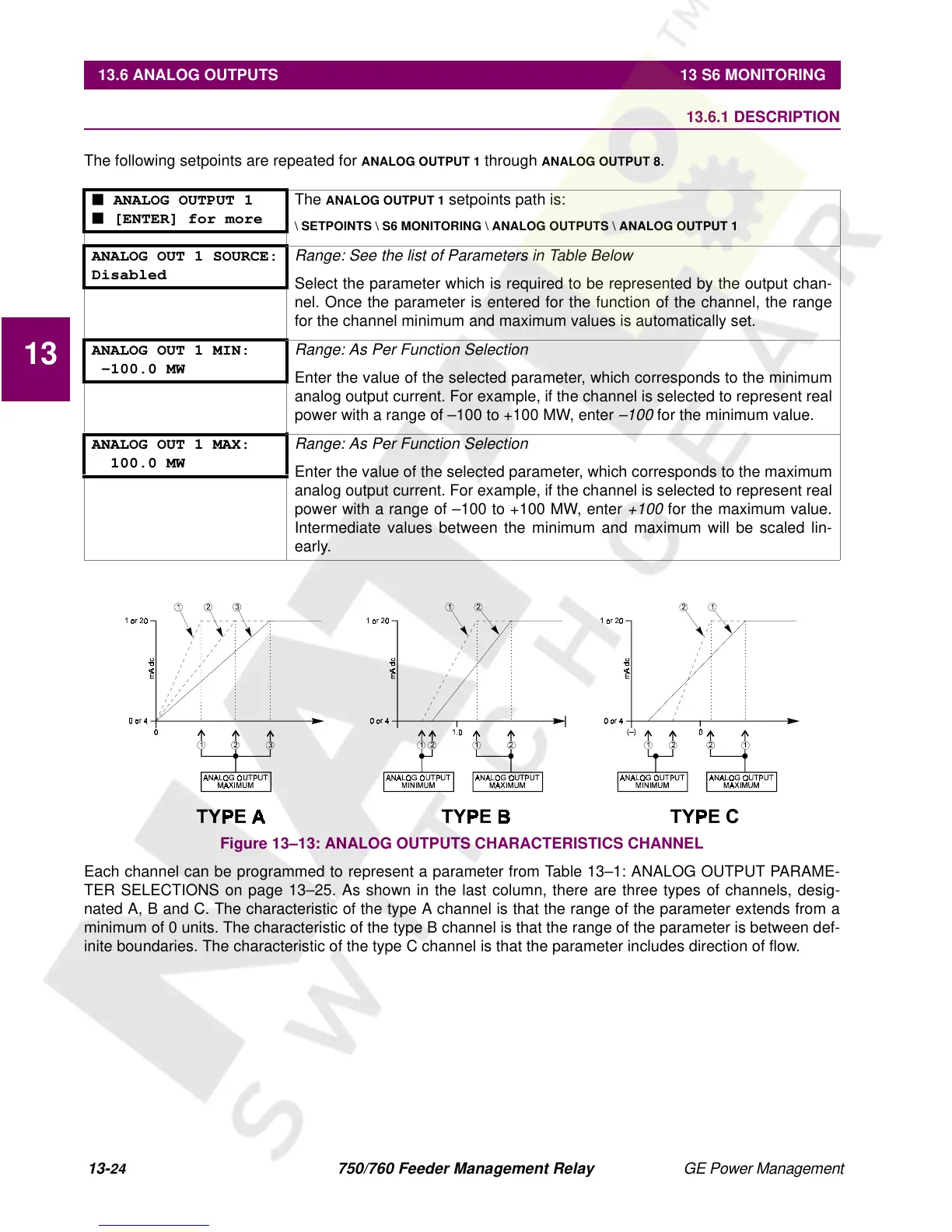
Figure 13–13: ANALOG OUTPUTS CHARACTERISTICS CHANNEL
Each channel can be programmed to represent a parameter from Table 13–1: ANALOG OUTPUT PARAME-
TER SELECTIONS on page 13–25. As shown in the last column, there are three types of channels, desig-
nated A, B and C. The characteristic of the type A channel is that the range of the parameter extends from a
minimum of 0 units. The characteristic of the type B channel is that the range of the parameter is between def-
inite boundaries. The characteristic of the type C channel is that the parameter includes direction of flow.
■ ANALOG OUTPUT 1
■ [ENTER] for more
The
ANALOG OUTPUT 1
setpoints path is:
\ SETPOINTS \ S6 MONITORING \ ANALOG OUTPUTS \ ANALOG OUTPUT 1
ANALOG OUT 1 SOURCE:
Disabled
Range: See the list of Parameters in Table Below
Select the parameter which is required to be represented by the output chan-
nel. Once the parameter is entered for the function of the channel, the range
for the channel minimum and maximum values is automatically set.
ANALOG OUT 1 MIN:
-100.0 MW
Range: As Per Function Selection
Enter the value of the selected parameter, which corresponds to the minimum
analog output current. For example, if the channel is selected to represent real
power with a range of –100 to +100 MW, enter
–100
for the minimum value.
ANALOG OUT 1 MAX:
100.0 MW
Range: As Per Function Selection
Enter the value of the selected parameter, which corresponds to the maximum
analog output current. For example, if the channel is selected to represent real
power with a range of –100 to +100 MW, enter
+100
for the maximum value.
Intermediate values between the minimum and maximum will be scaled lin-
early.
 Loading...


