16-
6
750/760 Feeder Management Relay GE Power Management
16.3 MODBUS PROTOCOL 16 COMMUNICATIONS
16
16.3.5 FUNCTION CODE 01H/02H: READ BINARY STATUS
These function codes allow the master to read one or more consecutive binary status bits from an 750/760.
The status bits are packed into bytes with the first addressed bit occupying the least significant bit position of
the first returned byte. Enough bytes are returned to contain all requested status bits. The last byte is zero-pad-
ded as required. The maximum number of status bits that can be read in a single request is 1920 (although this
greatly exceeds the number of status bits defined in the 750/760).
The addresses of the bits that can be read using these functions are the same as the point indices defined for
the DNP Binary Input objects (e.g., address zero references the “Relay In Service” status). Refer to Section
16.5: DNP 3.0 DEVICE PROFILE on page 16–84 for the definition of all binary status data. Note that function
codes 01H and 02H are identical in their operation.
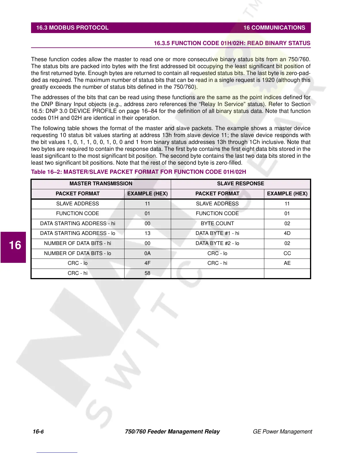
The following table shows the format of the master and slave packets. The example shows a master device
requesting 10 status bit values starting at address 13h from slave device 11; the slave device responds with
the bit values 1, 0, 1, 1, 0, 0, 1, 0, 0 and 1 from binary status addresses 13h through 1Ch inclusive. Note that
two bytes are required to contain the response data. The first byte contains the first eight data bits stored in the
least significant to the most significant bit position. The second byte contains the last two data bits stored in the
least two significant bit positions. Note that the rest of the second byte is zero-filled.
Table 16–2: MASTER/SLAVE PACKET FORMAT FOR FUNCTION CODE 01H/02H
MASTER TRANSMISSION SLAVE RESPONSE
PACKET FORMAT EXAMPLE (HEX) PACKET FORMAT EXAMPLE (HEX)
SLAVE ADDRESS 11 SLAVE ADDRESS 11
FUNCTION CODE 01 FUNCTION CODE 01
DATA STARTING ADDRESS - hi 00 BYTE COUNT 02
DATA STARTING ADDRESS - lo 13 DATA BYTE #1 - hi 4D
NUMBER OF DATA BITS - hi 00 DATA BYTE #2 - lo 02
NUMBER OF DATA BITS - lo 0A CRC - lo CC
CRC - lo 4F CRC - hi AE
CRC - hi 58