Chapter 3 Page no. 148
Component-index-intro.fm
GE Healthcare Senographe DS
Revision 1 Service Information and Procedures Class A 2385072-16-8EN
FRU/Component Index
3 COMPONENT INDEX TABLE SORT ORDER
The component index tables list components in order, according to main sub-assembly, class, and
alpha-numeric component description.
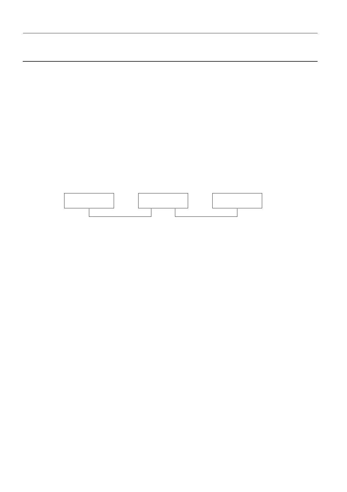
3-1 Main sub-assemblies
• The Senographe DS consists of three main sub-assemblies:
- Control Station
-Gantry
- Generator
• Each component forms part of one of these main sub-assemblies, and the component index includes
three tables, one for each sub-assembly.
• Cables connecting two sub-assemblies are allocated to one sub-assembly or another as shown.
Except for the X-ray Console cable, no cables pass directly between the Control Station and the
Generator Cabinet.
3-2 Component Class
Within each sub-assembly, components are sorted according to their class code (see Class on page
145).
3-3 Component Description
Within each class, components are sorted by component description, in alphanumeric order.
Control Station Gantry Generator
Allocated to Control Station Allocated to Gantry
 Loading...


