GE Healthcare Senographe DS
Revision 1 Service Information and Procedures Class A 2385072-16-8EN
Job Card ELE A010 - Set Lift Travel Limits
Page no. 565 Chapter 7
JC-ELE-A-010.fm
Job Card ELE A010 - Set Lift Travel Limits Chapter 7
1SUPPLIES
None
2TOOLS
Standard Tool Box
3 REQUIRED EFFORT
Personnel: 1 Field Engineer
Time: 15 minutes
4 SAFETY PRECAUTION
No specific safety precautions are applicable.
5 PREREQUISITES
None
6 PROCEDURE
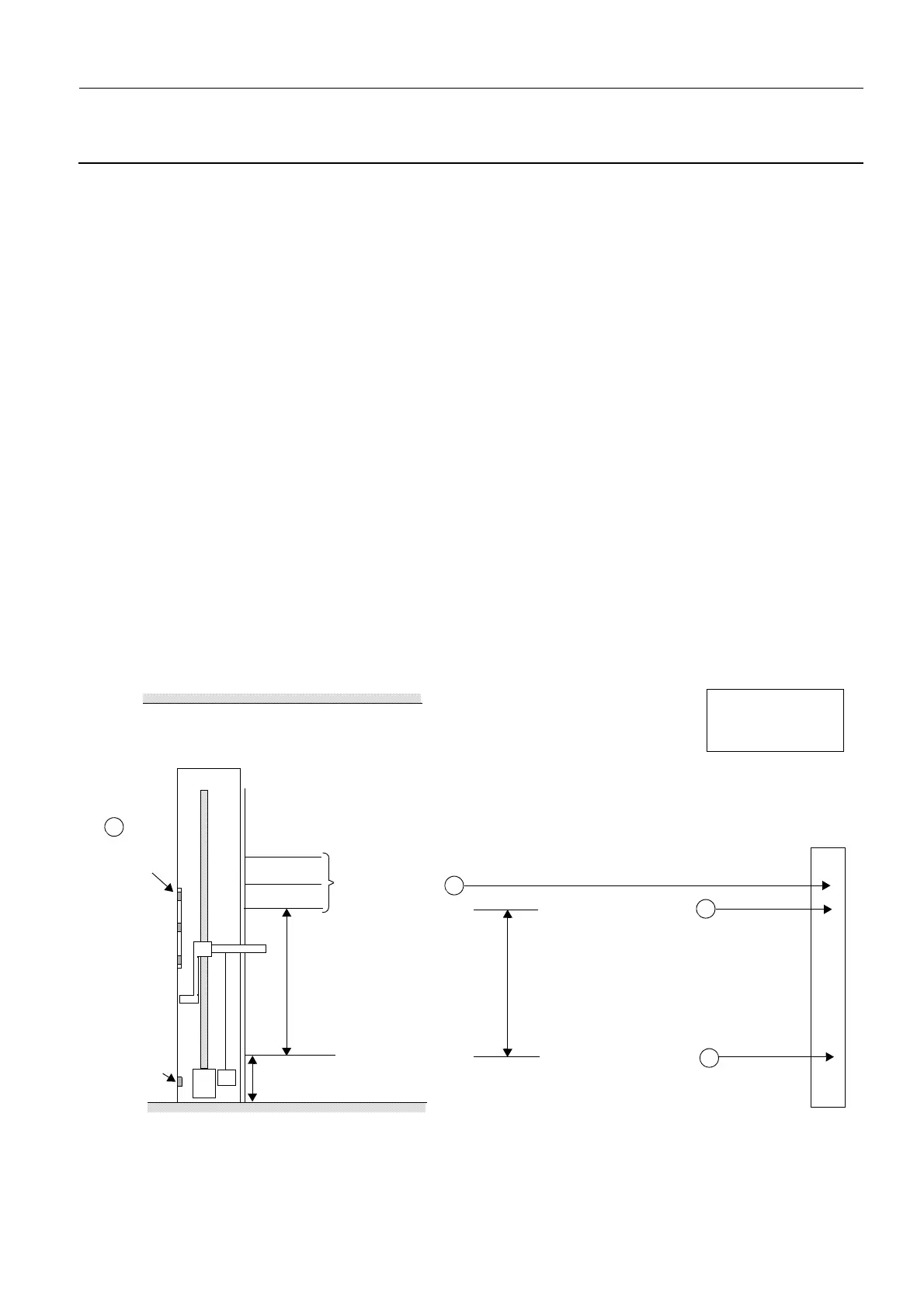
6-1 Principle
The illustration below highlights the important principles behind setting the lift travel limits.
Lower lift travel limit
Upper lift travel limit
Lift travel limit
Measured then set
Floor
Ceiling
Upper optical
fork position
Derived from the lift
travel limit plus the
lower lift travel limit
Set in the ADS soft-
ware and must corre-
spond to upper optical
fork position
Top
Middle
Bottom
Lift Potentiometer
Lower Reference Voltage
Lift Potentiometer
Upper Reference Voltage
650 mm — this automatic stop
distance during the calibration
phase is determined by the Lift
Encoder which accurately trans-
lates lift screw turns to height
traveled.
650 mm
750 mm
850 mm
1
2
4
Lift Board Firmware
Set with FOV
size button
3
Set with FOV
size button
670 ±2 mm
0mm
Lower optical
fork position
(fixed)
LE
LP
Key
LE: Lift Encoder
LP: Lift Potentiometer
 Loading...


