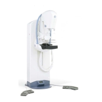
GE Healthcare Senographe DS
Revision 1 Service Information and Procedures Class A 2385072-16-8EN
Scenario ELE A001 - Electrical Installation
Page no. 537 Chapter 7
SC-ELE-A-001.fm
Scenario ELE A001 - Electrical Installation Chapter 7
1CONTEXT
This Scenario provides information for the electrical phase of a first installation of Senographe equip-
ment on the customer site.
The installation is split into two phases:
• Physical installation: positioning and cabling the various sub-systems without applying power. Refer
to chapter 6 Physical Installation on page 375.
• Electrical installation: powering on the system, configuration, and verification, up to start-up with the
customer. This is treated in this scenario.
2STEERING GUIDE
Refer to the following Steering Guide for an outline of the recommended sequence of electrical installa-
tion, followed by checks and calibration.
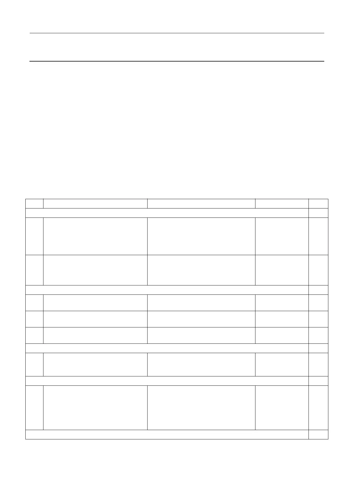
Electrical Installation Steering Guide:
Step Action Job Card Comments Done
Preparation
1 Check the review workstations in use
for first & second review vs IHE Mam-
mography Image Profile compliance.
Make decision with customer to
upgrade ADS SW
See OM Addendum (5427687-1-199)
2 Contact your local OLC to schedule
Insite Checkout; request modem
address and software keys
Contact printer supplier representative
Preliminary Power-up
3 Check supply voltages Job Card ELE A005 - Check Supply
Voltages on page 541
4 First System Power-up Job Card ELE A006 - First System
Power-On on page 543
5 Carry out line resistance check Job Card ELE A007 - Line Resistance
Measurement on page 547
Optional 21-inch 3 MP Monitor configuration
6 If the Senographe system has the 21-
inch 3 MP Monitor option, configure
the monitor resolution
Job Card ELE A008 - Configuring the
21-inch 3MP Monitor on page 549
Only perform if the
system has the 21-
inch 3 MP monitor
Install Image Receptor
7 Unpack/Install Image Receptor, add
coolant, check for leaks and install
detector covers
Job Card ELE A060 - Image Receptor
Installation on page 781
Configuration
 Loading...


