GE Healthcare Senographe DS
Revision 1 Service Information and Procedures Class A 2385072-16-8EN
Job Card D/R A407 - Generator Interface Board 400-PL2
Page no. 1577 Chapter 9
JC-DR-A-407.fm
Job Card D/R A407 - Generator Interface Board 400-PL2 Chapter 9
1SUPPLIES
• Generator Interface Board 400-PL2
2TOOLS
• Standard Tool Box
3 REQUIRED EFFORT
Personnel: 1 Field Engineer
Time: 90 minutes
4 SAFETY PRECAUTIONS
Steps in this Job Card tell you when to take appropriate action to avoid electric shock.
5 PREREQUISITES
None
6 PROCEDURE
6-1 Removal of the Generator Interface Board 400-PL2
1. Switch off the electrical power supply from the Mains Distribution Panel in the room. Apply an appro-
priate LOTO padlock and label. Wait 10 minutes for the components within the Generator to dis-
charge.
2. Remove the four Generator side panels (see Job Card PHY A042 - Remove/Reinstall Generator
Covers on page 513) to reveal the Generator Interface board 400-PL2.
3. Switch off the electrical power supply on the rotary switch in the Generator cabinet (position 0).
4. Using a voltmeter (rating 1000 V DC), check that there is no residual voltage between screws S1 and
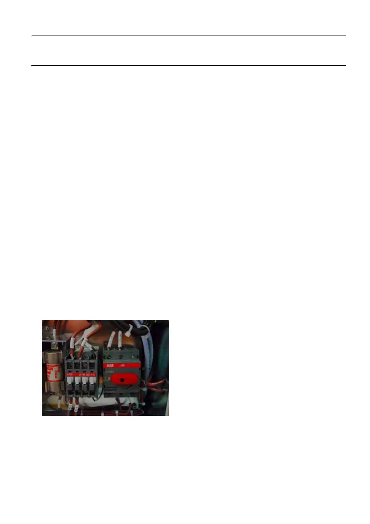 Loading...


