Context
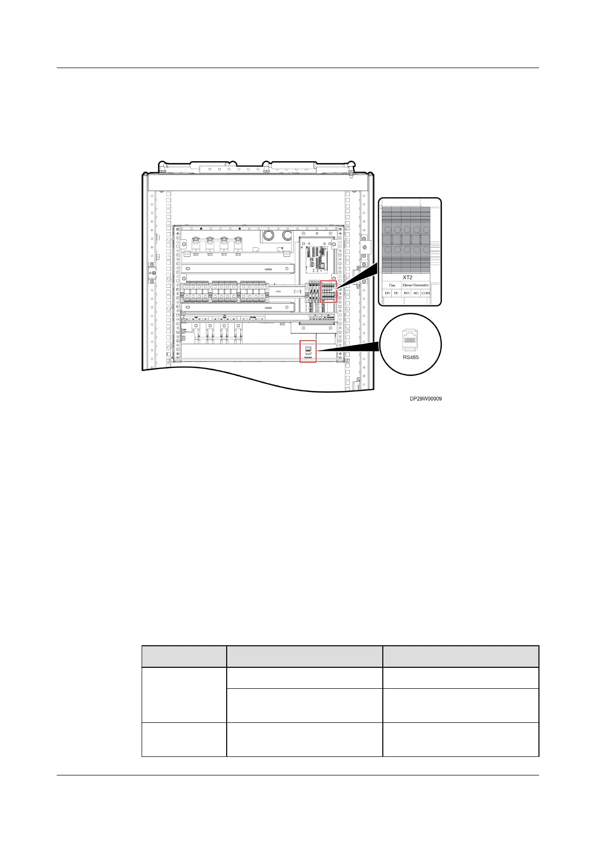
Figure 4-217 shows the ports on the ATS subrack.
Figure 4-217 Ports on the ATS subrack
(1) RS485 port (2) Fire port (re extinguishing
non-wiring terminal)
(3) Diesel Generator port (DG
signal wiring terminal)
Procedure
1. Connect a monitoring cable to the RS485 port on the ATS subrack.
2. (Optional) Connect a
re extinguishing non-monitoring cable.
3. (Optional) Connect a DG monitoring cable.
4.4 Verifying the Installation
Smart Cooling Product Installation Check
Table 4-15 Indoor unit installation checklist
Item
Check That Check Result
Fan The fan is secured. □ Passed □ Failed
The fan has no foreign matter
inside.
□ Passed □ Failed
Liquid level
detector
The liquid level detector is
secured.
□ Passed □ Failed
FusionModule800 Smart Small Data Center
User Manual 4 Installation Guide
Issue 01 (2021-02-05) Copyright © Huawei Technologies Co., Ltd. 245
 Loading...