2-3
2 Installing the NB Unit and Connecting Peripheral Devices
NB-series Programmable Terminals Setup Manual(V107)
2-1 Installing the NB Unit
2
2-1-2 Installation onto the Operation Panel
Install the NB Unit by embedding it into the operation panel.
Use the metal kit and tool (a crosshead screwdriver) supplied with the Unit for installation.
Proceed the installation following the procedures below.
1
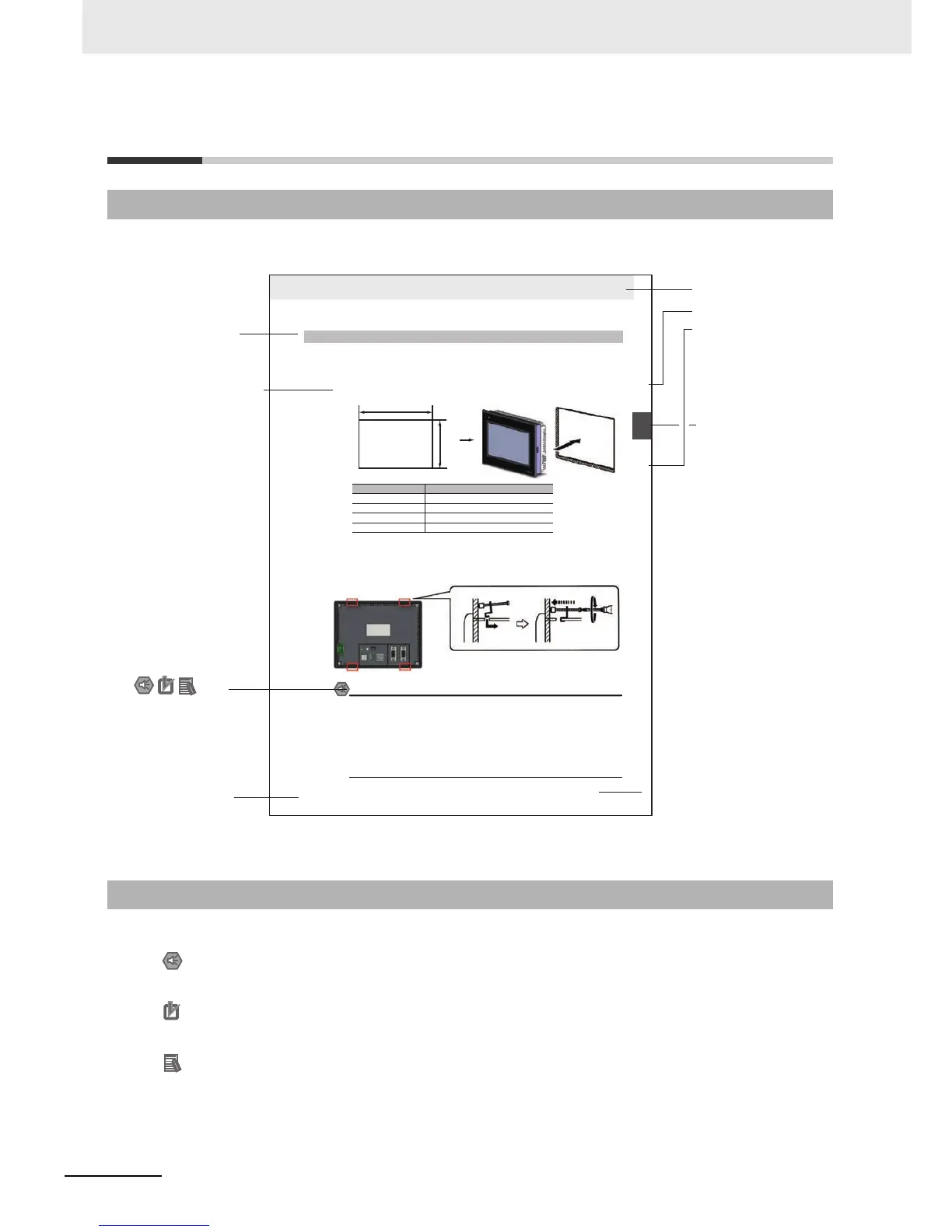
Panel cutout with dimensions is shown below. Fit the NB Unit into the panel from the front side.
2
As follows, insert panel fixators at the locations indicated by red box around the back of the NB Unit.
Insert the hooks of positioners into the square holes on the Unit to hold the fixators properly, and
tighten the screws firmly with the screwdriver.
NB5Q/NB7W-TWB
Precautions for Safe Use
• When operating on the operation panel, make sure to keep metal particles from entering the
Unit.
The mounting panel must be between 1.6 and 4.8 mm thick. The NB Unit must be installed
in a control panel.
For the sake of waterproof and dustproof, all the fixators must be evenly tightened to a
torque of 0.5~0.6 Nm. If the tightening torque exceeds the specified value, or the tightening
is not even, deformation of the front panel may occur.
Make sure that the operation panel is clean, unbent, and strong enough for the installation
process.
2-1-2 Installation onto the Operation Panel
Models Opening Dimension (W H mm)
NB3Q-TW00B/TW01B 119.0(+0.5/-0) 93.0(+0.5/-0)
NB5Q-TW00B/TW01B 172.4(+0.5/-0) 131.0(+0.5/-0)
NB7W-TW00B/TW01B 191.0(+0.5/-0) 137.0(+0.5/-0)
NB10W-TW01B 258.0(+0.5/-0) 200.0(+0.5/-0)
Opening dimensions
Width
Height
Level 1 heading
Level 2 heading
Level 3 heading
Step in a procedure
Manual name
Special Information
(See below.)
Level 3 heading
Page tab
Gives the current
headings.
Indicates a step in a
procedure.
Gives the number
of the section.
This illustration is provided only as a sample and may not literally appear in this manual.
Icons are used to indicate
precautions and
additional information.

 Loading...


