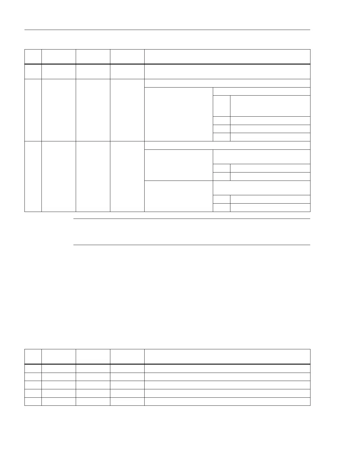
No. Parameter
mask
Parameter
internal
Data type Meaning
24 <_GMODE> INT Geometrical mode (evaluation of programmed geometrical data), re‐
served
25 <_DMODE> INT Display mode
UNITS: Machining plane G17/18/19
0 = Compatibility, the plane effective
before the cycle call remains ac‐
tive
1 = G17 (only active in the cycle)
2 = G18 (only active in the cycle)
3 = G19 (only active in the cycle)
26 <_AMODE> INT Alternative mode
UNITS: Drilling depth = Final drilling depth Z1
abs/inc
0 = Absolute
1 = Incremental
TENS: Absolute value / percentage DF for each
additional infeed (degression)
0 = Absolute value
1 = Percentage (0.001 to 100%)
Note
1)
Parameters 21, 22 and 23 are only used for thread selection in the screen form thread tables.
The thread tables cannot be accessed via cycle definition in the cycle run time.
3.25.1.20 CYCLE79 - multi-edge
Syntax
CYCLE79(<_RTP>, <_RFP>, <_SDIS>, <_DP>, <_NUM>, <_SWL>, <_PA>,
<_PO>, <_STA>, <_RC>, <_AP1>, <_MIDA>, <_MID>, <_FAL>, <_FALD>,
<_FFP1>, <_CDIR>, <_VARI>, <_FS>, <_ZFS>, <_GMODE>, <_DMODE>,
<_AMODE>)
Parameters
No. Parameter
mask
Parameter
internal
Data type Meaning
1 RP <_RTP> REAL Retraction plane (abs)
2 Z0 <_RFP> REAL Reference point of tool axis (abs)
3 SC <_SDIS> REAL Safety clearance (to be added to reference point, enter without sign)
4 Z1 <_DP> REAL Multiple-edge depth (abs/inc), see <_AMODE>
5 N <_NUM> INT Number of edges (1...n)
Work preparation
3.25 Programming cycles externally
NC programming
1062 Programming Manual, 12/2019, 6FC5398-2EP40-0BA0
 Loading...


