Points P1 to P4 have the following coordinates:
Position Coordinates
P1 X25 Z-7.5
P2 X40 Z-15
P3 X40 Z-25
P4 X60 Z-35
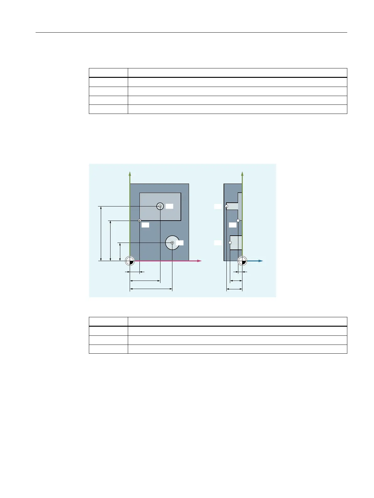
Example: Workpiece positions for milling
For milling, the feed depth must also be described, i.e. the third coordinate (in this case Z) must
also be assigned a numerical value.
33
3
3
3
3
<
;
<
=
Points P1 to P3 have the following coordinates:
Position Coordinates
P1 X10 Y45 Z-5
P2 X30 Y60 Z-20
P3 X45 Y20 Z-15
2.1.1.3 Polar coordinates
Polar coordinates can be used instead of Cartesian coordinates to describe workpiece
positions. This is useful when a workpiece or part of a workpiece has been dimensioned with
radius and angle. The point from which the dimensioning starts is called the "pole".
Position specifications in the form of polar coordinates
Polar coordinates are made up of the polar radius and the polar angle.
The polar radius is the distance between the pole and the position.
Fundamentals
2.1 Fundamental Geometrical Principles
NC programming
Programming Manual, 12/2019, 6FC5398-2EP40-0BA0 29
 Loading...


