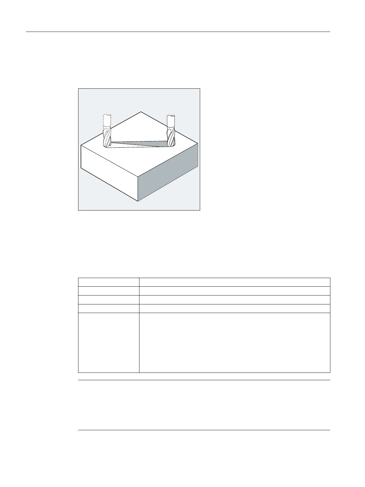
2.9.5 Linear interpolation (G1)
With G1 the tool travels on paraxial, inclined or straight lines arbitrarily positioned in space.
Linear interpolation permits machining of 3D surfaces, grooves, etc.
Syntax
G1 X… Y… Z … F…
G1 AP=… RP=… F…
Meaning
G1: Linear interpolation with feedrate (linear interpolation)
X... Y... Z...: End point in Cartesian coordinates
AP=...: End point in polar coordinates, in this case polar angle
RP=...: End point in polar coordinates, in this case polar radius
F...: Feedrate speed in mm/min. The tool travels at feedrate F along a straight line
from the current starting point to the programmed destination point. You can
enter the destination point in Cartesian or polar coordinates. The workpiece is
machined along this path.
Example: G1 G94 X100 Y20 Z30 A40 F100
The end point on X, Y, Z is approached at a feedrate of 100 mm/min; the rotary
axis A is traversed as a synchronized axis, ensuring that all four movements
are completed at the same time.
Note
G1 is modal.
Spindle speed S and spindle direction M3/M4 must be specified for the machining.
Axis groups, for which path feedrate F applies, can be defined with FGROUP. You will find more
information in the "Path behavior" section.
Fundamentals
2.9 Motion commands
NC programming
186 Programming Manual, 12/2019, 6FC5398-2EP40-0BA0
 Loading...


