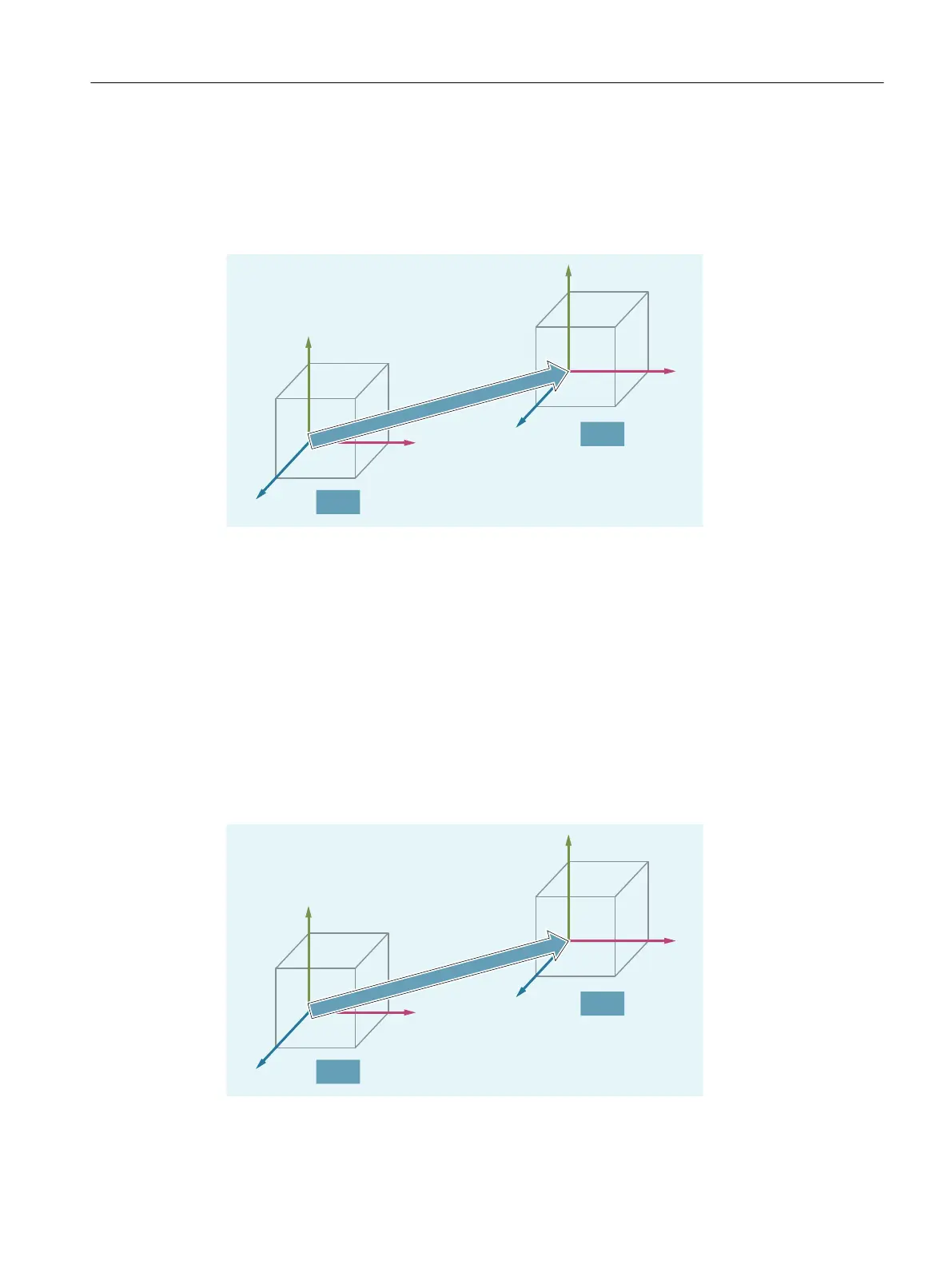
Machine tools with kinematic transformation
BCS and MCS do not coincide when the BCS is mapped onto the MCS with kinematics
transformation (e.g. 5-axis transformation, TRANSMIT/TRACYL/TRAANG).
On such machines the machine axes and geometry axes must have different names.
0&6
%&6
<
0&6
;
0&6
=
0&6
<
%&6
;
%&6
=
%&6
.LQHPDWLFWUDQVIRUPDWLRQ
Machine kinematics
The workpiece is always programmed in a two- or three-dimensional, right-angled coordinate
system (WCS). However, such workpieces are being programmed ever more frequently on
machine tools with rotary axes or linear axes not perpendicular to one another. Kinematic
transformation is used to represent coordinates programmed in the workpiece coordinate
system (rectangular) in real machine axis motion.
2.1.4.3 Basic zero system (BZS)
The basic zero system (BZS) is derived from the basic coordinate system through the basic
offset.
%&6
%=6
%DVLFRIIVHW
<
;
=
<
;
=
Fundamentals
2.1 Fundamental Geometrical Principles
NC programming
Programming Manual, 12/2019, 6FC5398-2EP40-0BA0 39
 Loading...


