No. Parameter
mask
Parameter
internal
Data type Meaning
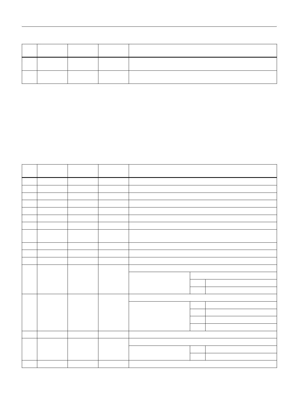
13 ZD <S_ZD> REAL Incremental remaining drilling depth in relation to final drilling depth or
absolute (see <_AMODE> TEN THOUSANDS)
14 FD <S_FD> REAL Remaining drilling feedrate as value or in % (in conjunction
with <_AMODE> HUNDRED THOUSANDS)
3.25.1.23 CYCLE83 – deep-hole drilling 1
Syntax
CYCLE83(<RTP>, <RFP>, <SDIS>, <DP>, <DPR>, <FDEP>, <FDPR>, <_DAM>,
<DTB>, <DTS>, <FRF>, <VARI>, <_AXN>, <_MDEP>, <_VRT>, <_DTD>,
<_DIS1>, <_GMODE>, <_DMODE>, <_AMODE>)
Parameter
No. Parameter
mask
Parameter
internal
Data type Meaning
1 RP <RTP> REAL Retraction plane (abs)
2 Z0 <RFP> REAL Reference point (abs)
3 SC <SDIS> REAL Safety clearance (to be added to reference point, enter without sign)
4 Z1 <DP> REAL Final drilling depth (abs), see <_AMODE>
5 Z1 <DPR> REAL Final drilling depth (inc), see <_AMODE>
6 D <FDEP> REAL 1st drilling depth (abs), see <_AMODE>
7 D <FDPR> REAL 1st drilling depth (inc), see <_AMODE>
8 DF <_DAM> REAL Degression value / percentage for each additional infeed,
see <_AMODE>
9 DTB <DTB> REAL Dwell time at drilling depth, see <_AMODE>
10 DTS <DTS> REAL Dwell time at start point (for chip removal only), see <_AMODE>
11 FD1 <FRF> REAL Percentage for the feedrate for the first infeed, see <_AMODE>
12 <VARI> INT Machining type
UNITS: Chip breaking/removal
0 = Chip breaking
1 = Swarf removal
13 <_AXN> INT Tool axis
0 = 3rd geometry axis
1 = 1st geometry axis
2 = 2nd geometry axis
> 2 3rd geometry axis
14 V1 <_MDEP> REAL Minimum infeed (only for degression percentage)
15 V2 <_VRT> REAL Retraction distance after each machining step (for chip breaking only)
> 0 Variable retraction distance
0 = Default value 1 mm
16 DT <_DTD> REAL Dwell time at final drilling depth, see <_AMODE>
Work preparation
3.25 Programming cycles externally
NC programming
1068 Programming Manual, 12/2019, 6FC5398-2EP40-0BA0
 Loading...


