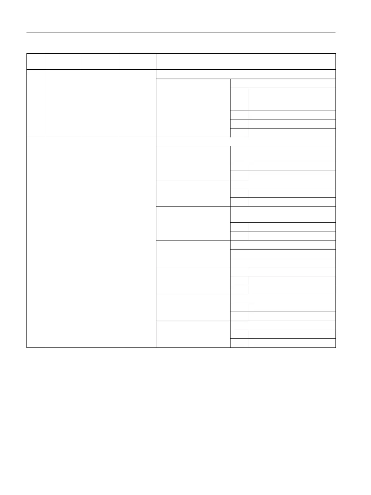
No. Parameter
mask
Parameter
internal
Data type Meaning
25 <_DMODE> INT Display mode
UNITS: Machining plane G17/G18/G19
0 = Compatibility, the plane effective
before the cycle call remains ac‐
tive
1 = G17 (only active in the cycle)
2 = G18 (only active in the cycle)
3 = G19 (only active in the cycle)
26 <_AMODE> INT Alternative mode
UNITS: Dimensioning for top of groove (for inter‐
face only)
0 = At the reference point
1 = Opposite the reference point
TENS: Depth
0 = Absolute
1 = Incremental
HUNDREDS: Dimensioning for width (for interface on‐
ly)
0 = At outer diameter (top)
1 = At inner diameter (bottom)
THOUSANDS: Radius/chamfer 1 (<_RCO1>)
0 = Radius
1 = Chamfer
TEN THOUSANDS: Radius/chamfer 2 (<_RCI1>)
0 = Radius
1 = Chamfer
HUNDRED THOUSANDS: Radius/chamfer 3 (<_RCI2>)
0 = Radius
1 = Chamfer
ONE MILLION: Radius/chamfer 4 (<_RCO2>)
0 = Radius
1 = Chamfer
3.25.1.42 CYCLE940 – undercut form E and F / undercut thread
Various undercuts can be programmed using the CYCLE940 cycle. In some cases, these differ
significantly regarding the parameterization.
The additional columns in the table indicate which parameters are required for which undercut
type. They correspond to the vertical selection softkeys in the cycle screen form:
● E: Undercut form E
● F: Undercut form F
Work preparation
3.25 Programming cycles externally
NC programming
1118 Programming Manual, 12/2019, 6FC5398-2EP40-0BA0
 Loading...


