Machining planes for turning/milling
Machining planes for turning
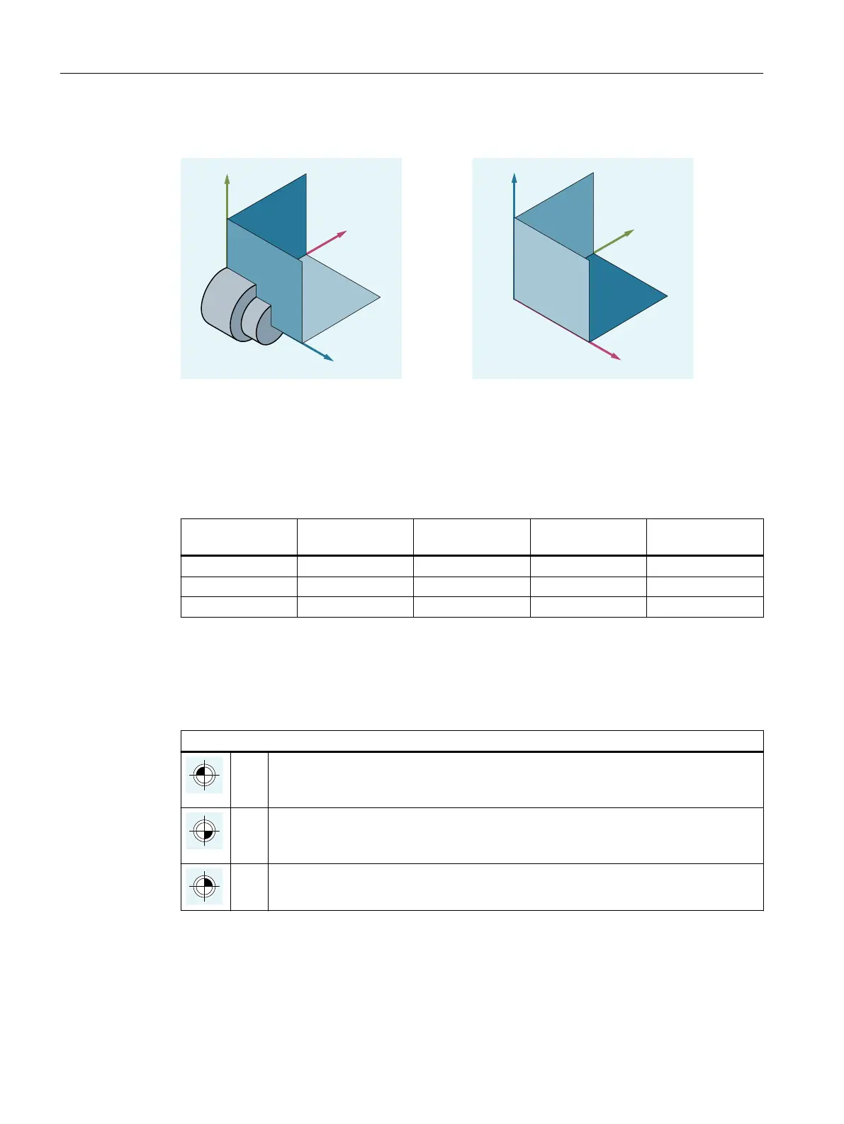
Machining planes for milling
Activating a machining plane
The machining planes are activated in the NC program using G commands G17, G18 and G19.
The relationship is defined as follows:
G command Machining plane Abscissa Ordinate Applicate ≙ infeed
direction
G17 X/Y X Y Z
G18 Z/X Z X Y
G19 Y/Z Y Z X
2.1.3 Zero points and reference points
Various zero points and reference points are defined on an NC machine:
Zero points
M Machine zero
The machine zero defines the machine coordinate system (MCS). All other reference
points refer to the machine zero.
W Workpiece zero = program zero
The workpiece zero defines the workpiece coordinate system in relation to the machine
zero.
A Blocking point
Can be the same as the workpiece zero (only for lathes).
Fundamentals
2.1 Fundamental Geometrical Principles
NC programming
34 Programming Manual, 12/2019, 6FC5398-2EP40-0BA0
 Loading...


