3C-52 Transfer: Motor-Shift Type (Transfer with Shift Actuator)
Voltage and Signal Check
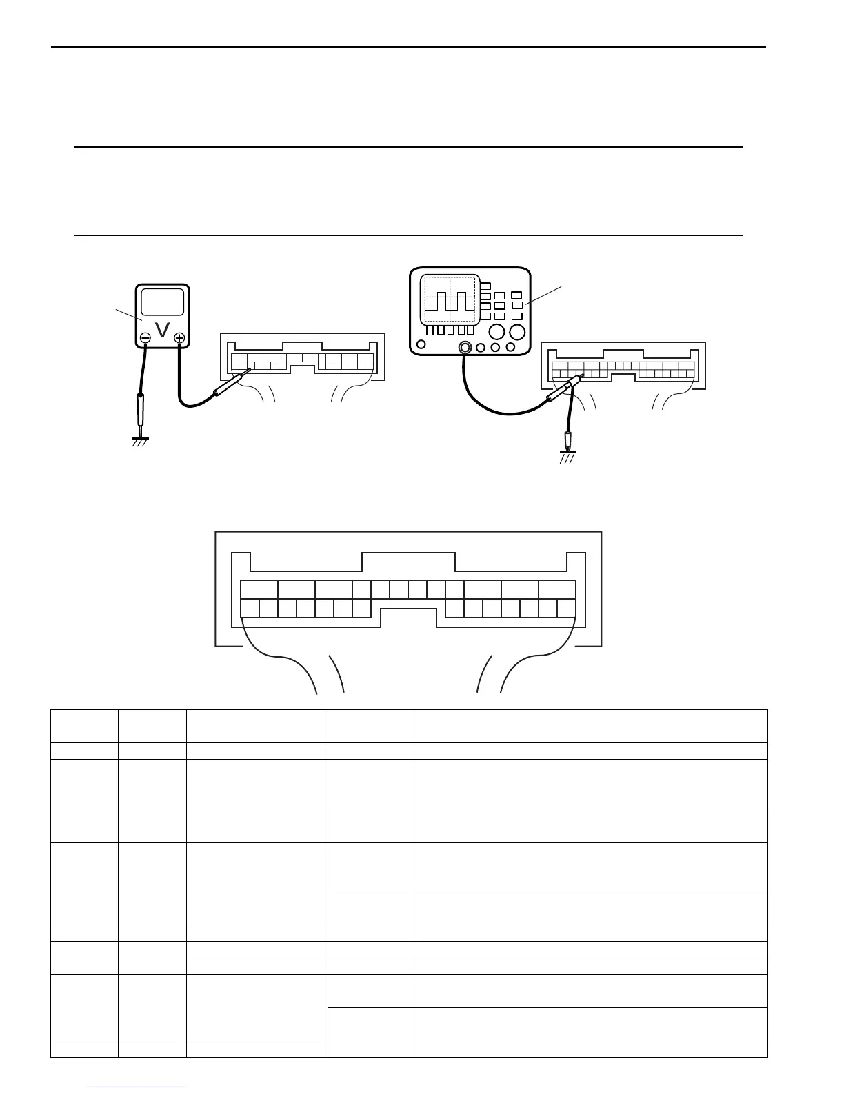
1) Check voltage using voltmeter (1) connected to each terminal of couplers.
2) Check signal using oscilloscope (2) connected to each terminal of couplers.
NOTE
• As each terminal voltage is affected by the battery voltage, confirm that it is 11 V or more when
ignition switch is turned ON.
• Pulse signal cannot be measured by voltmeter. It can be measured by oscilloscope.
• Item with asterisk (*) in normal voltage column can be read only by oscilloscope.
Terminal arrangement of 4WD control module connector (Viewed from harness side)
1
2
I4JA01332053-01
123456789101112
1314151617181920212223242526
I4JA01332054-01
Terminal
Number
Wire
Color
Circuit
Normal
Voltage
Condition
E91-1 BLK Ground 0 – 1 V —
E91-2 BLU
Transfer actuator
motor 1
10 – 14 V
Ignition switch turned to ON position and transfer shift
actuator being rotated N → 4H → 4H-lock direction or 4L-
lock → 4H-lock direction
0 – 1 V
Ignition switch turned to ON position and transfer shift
actuator in other than above-mentioned condition
E91-3 YEL
Transfer actuator
motor 2
10 – 14 V
Ignition switch turned to ON position and transfer shift
actuator being rotated 4H-lock → 4H → N direction or
4H-lock → 4L-lock direction
0 – 1 V
Ignition switch turned to ON position and transfer shift
actuator in other than above-mentioned condition
E91-4 — — — —
E91-5 — — — —
E91-6 — — — —
E91-7 BLK/ORN Clutch switch
10 – 14 V
Ignition switch turned to ON position and clutch pedal
released
0 – 1 V
Ignition switch turned to ON position and clutch pedal
kept depressing
E91-8 PNK Diagnosis switch 4 – 5 V Ignition switch turned to ON position

 Loading...


