Transfer: Motor-Shift Type (Transfer with Shift Actuator) 3C-53
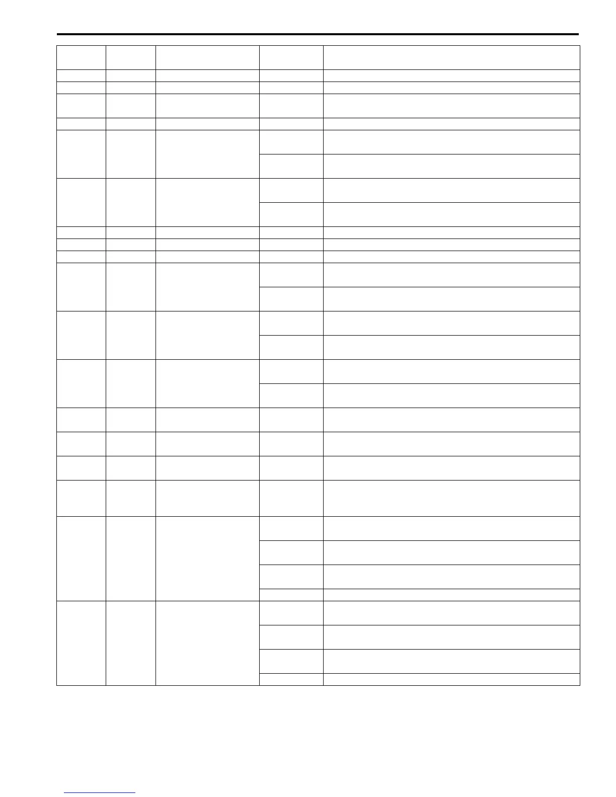
E91-9 — — — —
E91-10 BLK Ground 0 – 1 V —
E91-11 WHT
Power source for
internal memory
10 – 14 V —
E91-12 BLK/WHT Ignition switch 10 – 14 V Ignition switch turned to ON position
E91-13 BLK/WHT 4L/N switch
10 – 14 V
Ignition switch turned to ON position and transfer shifted
to 4H or 4H-lock position
0 – 1 V
Ignition switch turned to ON position and transfer shifted
to 4L-lock or N position
E91-14 RED/GRN
Center differential lock
switch
10 – 14 V
Ignition switch turned to ON position and transfer shifted
to 4H-lock or 4L-lock position
0 – 1 V
Ignition switch turned to ON position and transfer shifted
to N or 4H position
E91-15 — — — —
E91-16 — — — —
E91-17 — — — —
E91-18 LT GRN Transfer switch 1
10 – 14 V
Ignition switch turned to ON position and transfer switch
at 4H, N or 4L-lock position
0 – 1 V
Ignition switch turned to ON position and transfer switch
at N position
E91-19 BLU/BLK Transfer switch 2
10 – 14 V
Ignition switch turned to ON position and transfer switch
at 4L-lock position
0 – 1 V
Ignition switch turned to ON position and transfer switch
at 4H, 4H-lock or N position
E91-20 BLU/ORN Transfer switch 3
10 – 14 V
Ignition switch turned to ON position and transfer switch
at 4H or N position
0 – 1 V
Ignition switch turned to ON position and transfer switch
at 4H-lock or 4L-lock position
E91-21 PPL/WHT
Data link connector
(DLC)
10 – 14 V Ignition switch turned to ON position
E91-22 RED
CAN communication
line (High)
*2.5 – 3.5 V Ignition switch turned to ON position
E91-23 WHT
CAN communication
line (Low)
*1.5 – 2.5 V Ignition switch turned to ON position
E91-24 BLK/YEL
Transfer actuator
position switch
(ground)
0 – 1 V —
E91-25 RED
Transfer actuator
position switch 1
(power)
Approx. 4 V
Ignition switch turned to ON position and transfer shifted
to 4H-lock position
Approx. 2 V
Ignition switch turned to ON position and transfer shifted
to 4H position
Approx. 1 V
Ignition switch turned to ON position and transfer shifted
to 4L-lock or N position
Approx. 0 V Ignition switch turned to OFF position
E91-26 RED/BLK
Transfer actuator
position switch 2
(power)
Approx. 4 V
Ignition switch turned to ON position and transfer shifted
to 4L-lock position
Approx. 2 V
Ignition switch turned to ON position and transfer shifted
to N position
Approx. 1 V
Ignition switch turned to ON position and transfer shifted
to 4H or 4H-lock position
Approx. 0 V Ignition switch turned to OFF position
Terminal
Number
Wire
Color
Circuit
Normal
Voltage
Condition

 Loading...


