Removal Procedure
Purpose
The purpose is to repack the 8830 Printer and
the 8830 Controller (if present) for removal by
Delivery / Removal Carriers.
8830 Printer Repack Kit
Kit Contents
673K34330
Inspect the shipment for the following items:
• Poly Tape
• Bubble Pack
• Foam Pads (2
• Cable Ties (2)
• Tape
• Box
• Bag (Poly)
• Bag (36 x 36)
• Bag (Jiffy)
• Photoreceptor End Caps (L & R)
8830 Controller Repack Kit
673K34340
Kit Contents
Inspect the shipment for the following items:
• Tape
• Box
• Bag (Anti-static)
• End Caps (Top & Bottom)
Preparation
1. Switch off the Main Power Switch and
disconnect the Power Cord.
2. Remove ail rolls of media and leave them
with the customer. Tape down the Roll
Support Tubes in their respective Drawer.
3. Remove the Power Cord and place it in a
Media Supply Drawer.
4. Remove the Catch Tray and the Catch Tray
Supports.
5. Place the Catch Tray into the (36 x 36)bag
and secure the bag with tape in three places.
Put the bag in the box and seal the flaps with
tape.
6. Put the two Catch Tray Supports into the
Poly Bag, close the flap, and secure the bag
with tape.
7. Put the bag into the Jiffy bag, close the flap,
and secure the bag with tape in three places.
8. If the Printer you are removing has the 8830
Controller, perform the following:
a. Remove the 8830 Controller by
removing the two screws and lifting it off
the groove at the bottom of the of
Printer.
b. Disconnect A1J3 on the 8830 Controller
panel from A1P3 on the Main PWB.
c. Disconnect the 8830 Controller ribbon
cable from J307B on the Main PWB.
d. Place the 8830 Controller in the Anti-
static Bag, install the Top and Bottom
End Caps, and place the assembly into
the box.
e. Secure the box with tape.
9. Using the Developer Material procedure
(REP 9.7), remove the Developer Material.
10. Reassemble the Developer Module and
reinstall it into the Printer. Engage the Gear
Lock.
11. Reinstall the Developer Module Side Cover.
12. Unlock the casters.
13. Open the Front Door and the Rear Door.
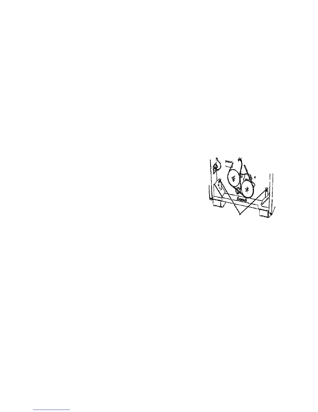
14. (Figure 1): Raise the leveling bolts.
01731
Figure 1. Raising the Leveling Bolts
Removal
1/98
6-26
8830
2
Repeat step 1 at
the other end of the
Printer
1
Rotate bolts fully
counterclockwise
 Loading...