REP 4.1.10 Control PWB
Parts List on PL 1.2
Removal
WARNING
Switch off the Scanner and disconnect the Power
Cord.
1. Switch off the SIM/XPC or host computer and the Scanner.
2. Remove the Right Side Panel (REP 4.1.1).
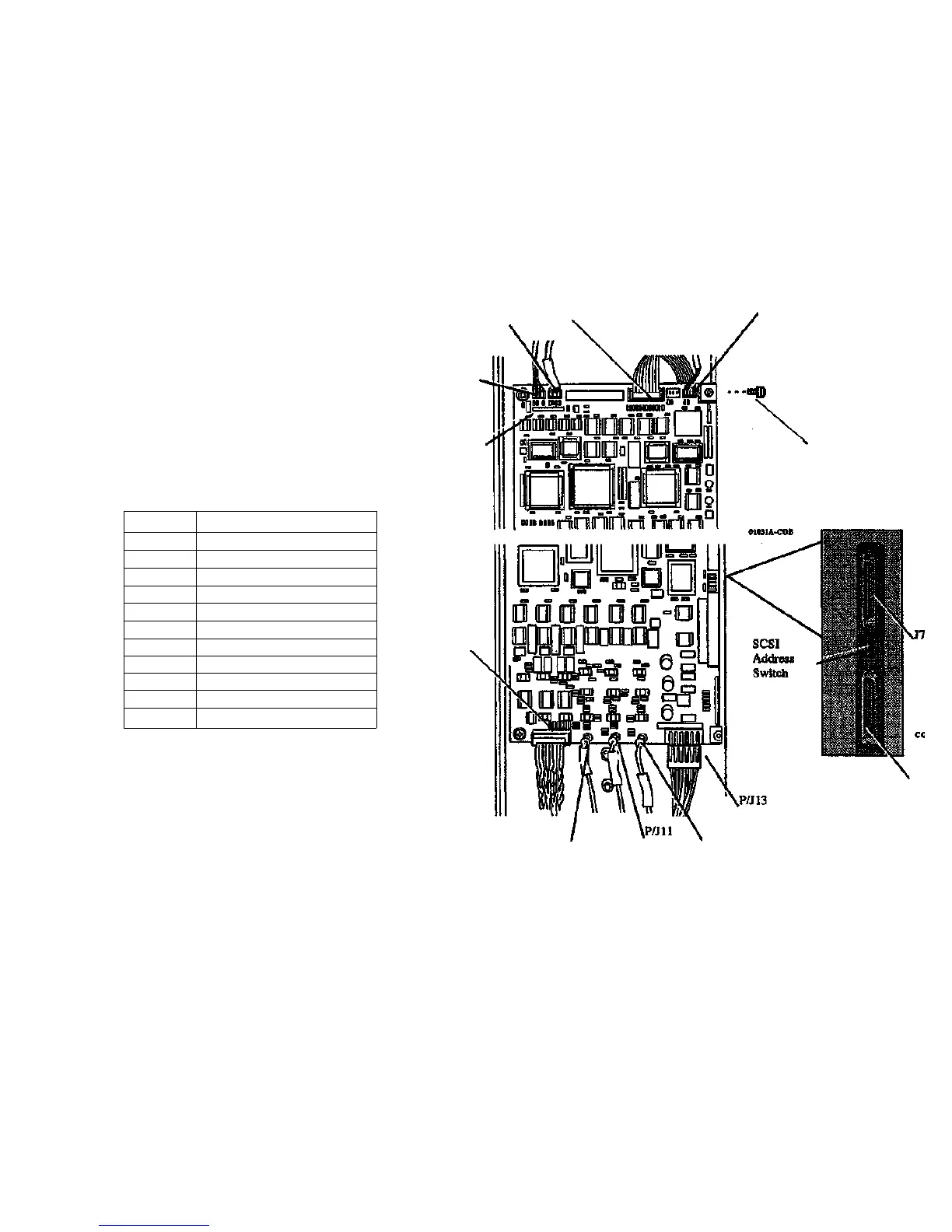
3. (Figure 1): Remove the Control PWB.
a. Disconnect the connectors shown in Table 1.
Table 1. Connectors on the Control PWB
P/J2
P/J4
P/J6
P/Jl
Standoff
Attachment
Screw (3)
External
Mounting
Screw (3)
Connector
P1
P2
P4
P6
P7
P8
P13
P12
P11
P1O
P9
Function
Sensor 1 (Edge Present Sensor)
Forward/Reverse Switch
Motor/Lamp control
Sensor 2 (Edge Registered Sensor)
SCSI Connector
SCSI Connector
Power Entry
Camera 1 video (cable 10168-001)
Camera 2 video (cable 10167-001)
Camera 3 video (cable 10168-001)
Camera Control Cable
P/J9
b.
c.
d.
Note:
Remove and keep the 3 External Mounting Screws with flat
washers and lock washers.
Remove and keep the 3 Standoff Attachment Screws with flat
washers and lock washers.
Remove the existing Control PWB.
Remove the top external mounting screw last to avoid
J8
01032A-COB
P/J10
P/J12
excessive stress when only one screw retains the PWB.
Figure 1. Top and Bottom Edge - Control PWB
7356 SCANNER
4/97
4-15
REP 4.1.10
 Loading...