ADJ 4.1.4 Left to Right Stitch
Purpose
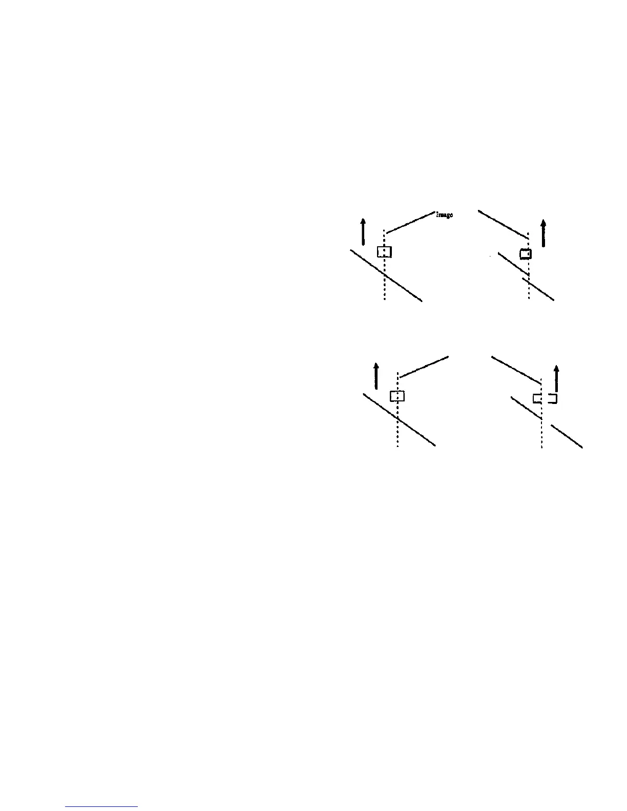
The purpose is to compensate for the variations in the left to right
position of Camera 1 and Camera 3 with respect to Camera 2. See
Figure 1.
Procedure
Note: This procedure uses the SCSI 7356 software as loaded onto a
Personal Workstation or other personal computer directly connected to
the Scanner. If the controlling system has Its own built-in diagnostics,
see the service manual for the controlling system.
Check
1. Start the diagnostic software, using the procedure appropriate for
the system to which the Scanner is connected.
Go to Section 6 for more information.
2. Select the Stitch Alignment button from the Service Diagnostic
Menu screen.
3. Insert the 082E11490 Test Pattern long edge first, and ensure that
the test pattern is captured by the document roll nip.
4. Select the L/R Stitch button.
5. Select the Begin button.
Note: The software check the timing of the sensor actuation, and
stores new correction values automatically if not correct The screen
displays Passed If the adjustment was successful; otherwise, FAILED is
displayed. If FAILED is displayed, refer to Section 2, Repair Analysis
Procedures.
Adjustment
Adjustment occurs automatically.
Stitch area of
Camera 1
Camera 2
image
Camera 1
image
Correct
Stitch area of
Image
Camera 2
image
Not Correct
Camera 1
image
Camera 2
image
Camera 1
image
' Camera 2
image
Figure 1. Image Example - Left to Right Stitch Adjustment
ADJ 4.1.3
4/97
4-42
7356 SCANNER
Correct
Not Correct
 Loading...