7-13
FUEL INJECTION SYSTEM
FI
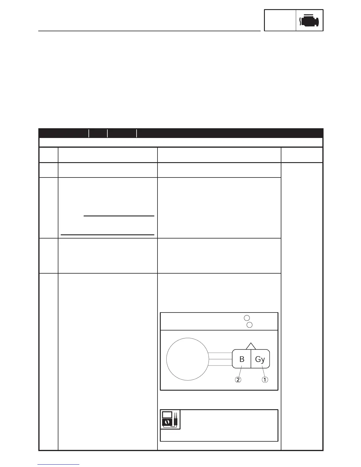
Crankshaft position sensor
resistance
248 X 372 Ω at 20_C (68_F)
(between gray and black)
Tester positive probe ! gray
Tester negative probe ! black
1
2
When installing or removing the con-
nector, main switch turn to “OFF”.
NOTE:
EAS00908
TROUBLESHOOTING DETAILS
This section describes the countermeasures per fault code number displayed on the meter. Check and
service the items or components that are the probable cause of the malfunction following the order.
After the check and service of the malfunctioned part has been completed, reset the meter display ac-
cording to the “Reinstatement method”.
Fault code No.:
Fault code number displayed on the meter when the engine failed to work normally. (Refer to the
“Fault code table”.)
Diagnostic code No.:
Diagnostic code number to be used when the diagnostic mode is operated. (Refer to “DIAGNOSTIC
MODE”.)
Fault code No. 12 Symptom No normal signals are received from the crankshaft position sensor.
Used diagnostic code No. – –
Order Inspection operation item and probable
cause
Operation item and countermeasure Reinstatement
method
1 Installed condition of sensor. Check the installed area for looseness or
pinching.
Reinstated by
cranking the
2 Connected condition of connector.
Inspect the coupler for any pins that
may have pulled out.
Check the locking condition of the
coupler.
If there is a malfunction, repair it and connect it
securely.
Crankshaft position sensor coupler
Main wiring harness ECU coupler
engine.
3 Open or short circuit in wiring harness. Repair or replace if there is an open or short
circuit between the main wiring harnesses.
Between sensor coupler and ECU coupler.
Gray - Gray
Black/Blue - Black / Blue
4 Defective crankshaft position sensor. Replace if defective.
1. Disconnect the crankshaft position sensor cou-
pler from the wire harness.
2. Connect the pocket tester (Ω 100) to the
crankshaft position sensor coupler as shown.
3. Measure the crankshaft position sensor resis-
tance.
4. Is the crankshaft position sensor OK?
 Loading...