2-36
CABLE ROUTING
SPEC
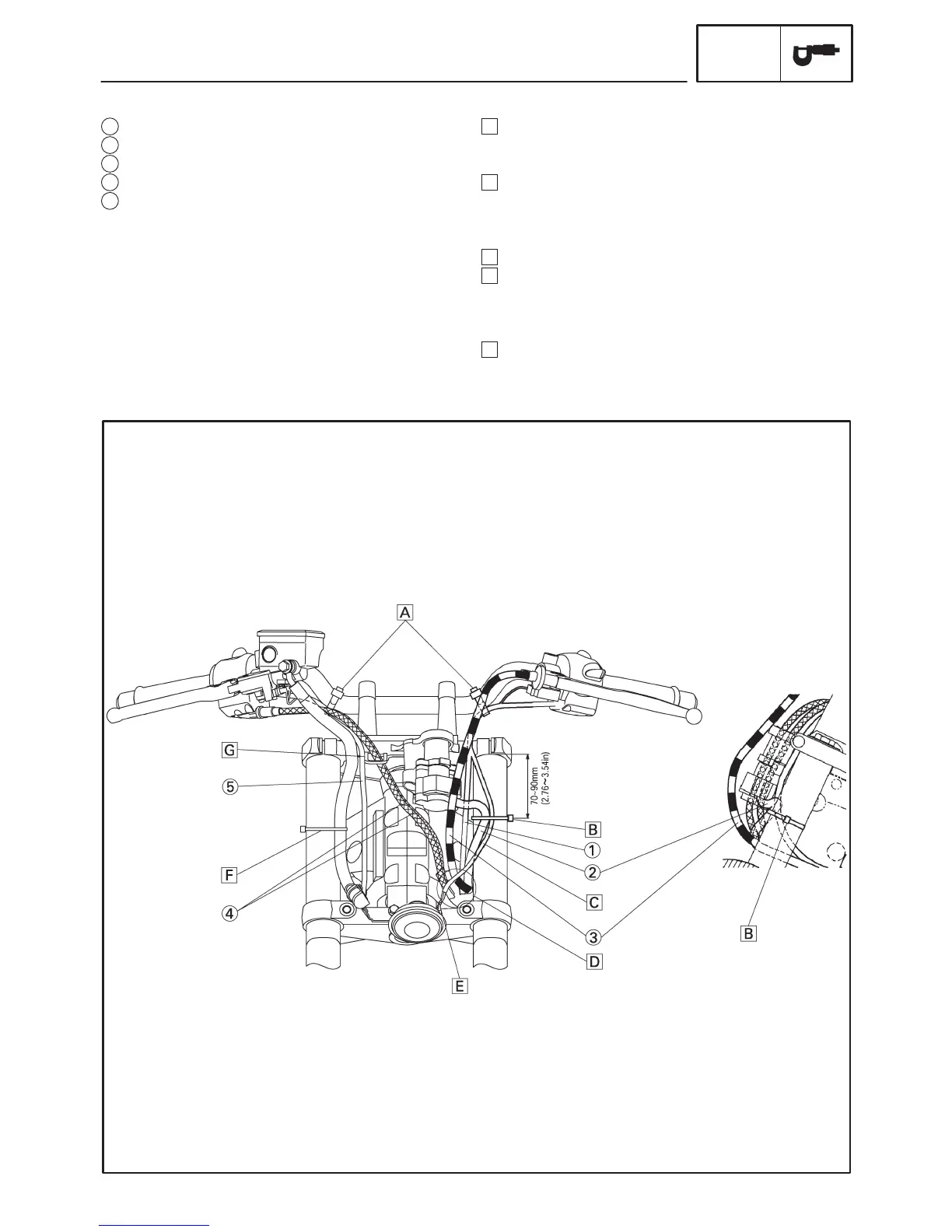
A Clamp the right and left handlebar switch leads and
handlebars. Point the tip of the clamp downward in
front of the handlebars.
B Clamp the horn lead and main switch lead to the in-
ner tube. Point the binding section to the outside of
the vehicle body and cut the tip down to the length of
1 to 5 mm (0.04 to 0.20 in).
C Route the horn lead by the headmost side.
D Pass the throttle cables, wire harness lead, clutch
cable, main switch and immobilizer lead and left
handlebar switch lead in order through the frame
hole from the inner side of the vehicle.
E Point the lead, which comes from the terminal, to
the front side of the vehicle body.
1 Left handlebar switch lead
2 Main switch lead
3 Clutch cable
4 Throttle cables
5 Right handlebar switch lead
CABLE ROUTING
 Loading...