4-26
FRONT WHEEL
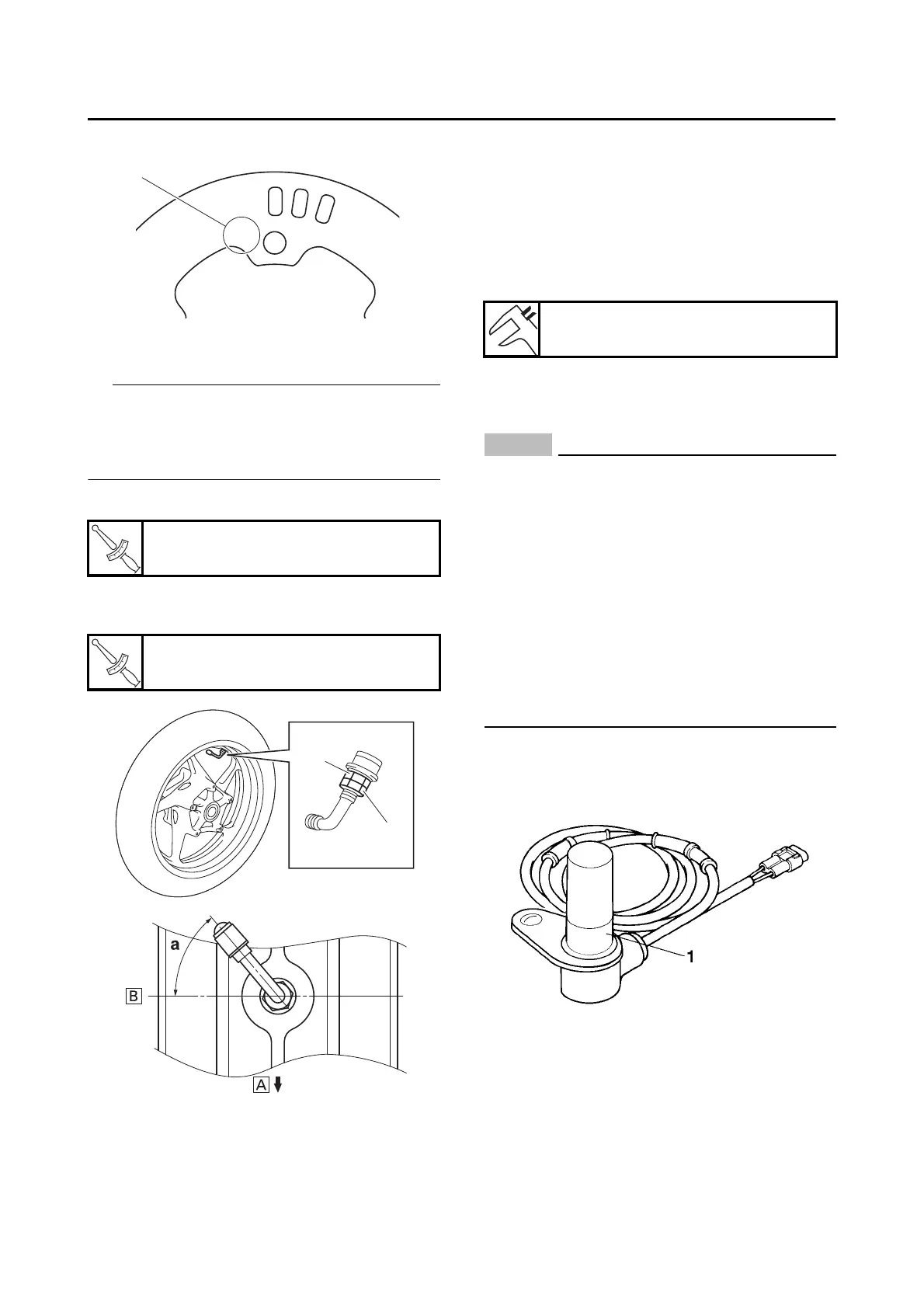
3. Install:
• Air valve
• Fasten air valve nut “1” and tighten air valve
locknut “2” to 3.0 N·m (0.30 kgf·m, 2.2 lb·ft).
• When installing the air valve, orient the air
valve referring to the illustration.
a. Tighten the air valve nut “1”.
b. Tighten the air valve locknut “2” while hold-
ing the air valve nut so as not to turn the nut.
4. Measure:
• Wheel sensor rotor runout
Out of specification Correct the wheel sen-
sor rotor runout or replace the wheel sensor
rotor.
Refer to “MAINTENANCE OF THE FRONT
WHEEL SENSOR AND SENSOR ROTOR”
on page 4-26.
EAS30155
MAINTENANCE OF THE FRONT WHEEL
SENSOR AND SENSOR ROTOR
ECA21070
• Handle the ABS components with care
since they have been accurately adjusted.
Keep them away from dirt and do not sub-
ject them to shocks.
• The front wheel sensor cannot be disas-
sembled. Do not attempt to disassemble it.
If faulty, replace with a new one.
• Keep any type of magnets (including mag-
netic pick-up tools, magnetic screwdrivers,
etc.) away from the front wheel sensor or
front wheel sensor rotor.
• Do not drop or shock the wheel sensor or
the wheel sensor rotor.
1. Check:
• Front wheel sensor “1”
Cracks/bends/distortion Replace.
Iron powder/dust Clean.
2. Check:
• Front wheel sensor rotor
Cracks/damage/scratches Replace the
front wheel sensor rotor.
Iron powder/dust/solvent Clean.
Front wheel air valve nut
2.0 N·m (0.20 kgf·m, 1.5 lb·ft)
Front wheel air valve locknut
3.0 N·m (0.30 kgf·m, 2.2 lb·ft)
a. 45–55
A. Wheel rotation direction
B. Left side
Wheel sensor rotor runout limit
0.25 mm (0.01 in)

 Loading...