5-31
CYLINDER AND PISTONS
EAS30289
REMOVING THE PISTON
The following procedure applies to all of the pis-
ton.
1. Remove:
• Piston pin clip
• Piston pin “1”
• Piston “2”
ECA13810
Do not use a hammer to drive the piston pin
out.
• Before removing the piston pin clip, cover the
crankcase opening with a clean rag to prevent
the piston pin clip from falling into the crank-
case.
• For reference during installation, put an identi-
fication mark on each piston crown.
• Before removing the piston pin, deburr the pis-
ton pin clip’s groove and the piston’s pin bore
area. If both areas are deburred and the piston
pin is still difficult to remove, remove it with the
piston pin puller set “3”.
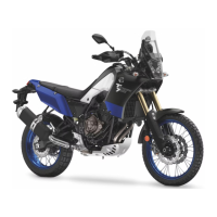
2. Remove:
• Top ring
• 2nd ring
•Oil ring
When removing a piston ring, open the end gap
with your fingers and lift the other side of the ring
over the piston crown.
EAS30291
CHECKING THE CYLINDERS AND PISTONS
The following procedure applies to all of the cyl-
inders and pistons.
1. Check:
• Piston wall
• Cylinder wall
Vertical scratches Replace the cylinder,
piston and piston rings as a set.
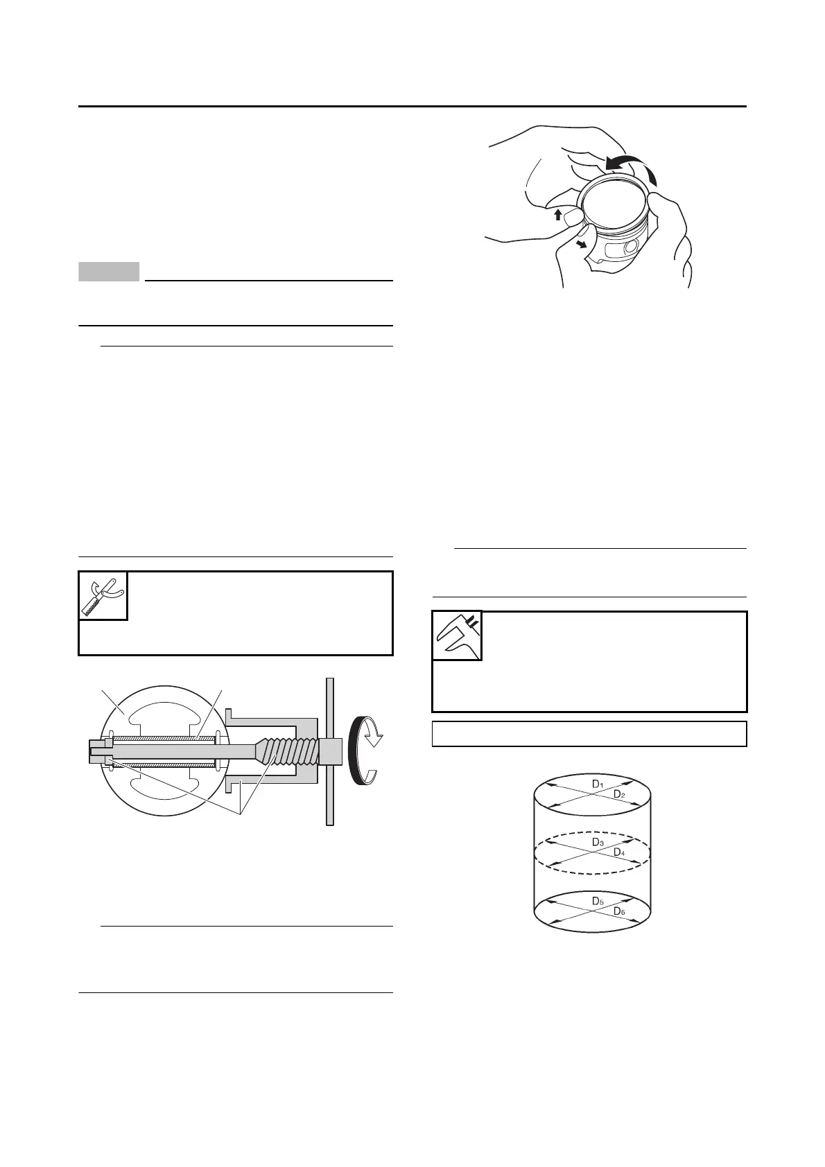
2. Measure:
• Piston-to-cylinder clearance
a. Measure cylinder bore with the cylinder
bore gauge.
Measure cylinder bore by taking side-to-side
and front-to-back measurements of the cylinder.
b. If out of specification, replace the cylinder,
piston and piston rings as a set.
c. Measure piston diameter “b” with the mi-
crometer.
Piston pin puller set
90890-01304
Piston pin puller
YU-01304
Bore
70.000–70.010 mm
(2.7559–2.7563 in)
Wear limit
70.060 mm (2.7583 in)
Bore = maximum of D
1
, D
2
, D
3
, D
4
, D
5
, D
6

 Loading...