8-106
ELECTRICAL COMPONENTS
b. Start the engine and let it run at approxi-
mately 5000 r/min.
c. Measure the rectifier/regulator input volt-
age.
EAS30573
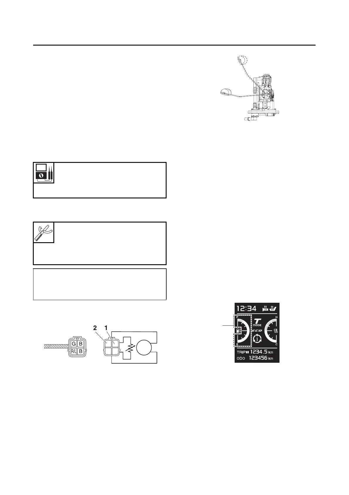
CHECKING THE FUEL SENDER
1. Remove:
• Fuel pump
(from the fuel tank)
Refer to “FUEL TANK” on page 7-1.
2. Check:
• Fuel sender resistance
Out of specification Replace the fuel
pump.
a. Connect the digital circuit tester () to the
fuel pump terminals as shown.
b. Move the fuel sender float to empty fuel
tank position “3” and full fuel tank position
“4” level position.
c. Measure the fuel sender resistance.
3. Install:
• Fuel pump
Refer to “FUEL TANK” on page 7-1.
EAS31557
CHECKING THE FUEL METER/FUEL LEVEL
WARNING INDICATOR
This model is equipped with a self-diagnosis
device for the fuel level detection circuit.
1. Check:
• Fuel meter/fuel level warning indicator “1”
(Push the ON/start switch.)
Fuel meter/fuel level warning indicator comes
on for a few seconds, then goes off Fuel
meter/fuel level warning indicator is OK.
Fuel meter/fuel level warning indicator does
not come on Replace the meter assembly.
Fuel meter/fuel level warning indicator flash-
es eight times, then goes off for 3 seconds in
a repeated cycle (malfunction detected in fuel
sender) Replace the fuel pump assembly.
EAS30577
CHECKING THE RADIATOR FAN MOTOR
1. Check:
• Radiator fan motor
Faulty/rough movement Replace.
a. Disconnect the radiator fan motor coupler
from the wire harness.
b. Connect the battery (DC 12 V) as shown.
Sender unit resistance (full)
10.0–14.0
Sender unit resistance (empty)
267.0–273.0
Digital circuit tester (CD732)
90890-03243
Model 88 Multimeter with
tachometer
YU-A1927
• Positive tester probe
Green “1”
• Negative tester probe
Black “2”

 Loading...